Windows Azure High Availability Options for SQL Server #Azure #Cloud #IaaS

Protecting against downtime associated with cloud outages is something that anyone deploying on ANY cloud service needs to address. While it could be easy to simply deploy your app in “the cloud” and assume that it is someone else’s problem to manage now, the reality is that while cloud providers probably have more resources and expertise to ensure your servers stay up, the ultimate responsibility to ensure that your critical application is available rests squarely on your shoulders.

Believe it or not, simply deploying your SQL Server in Windows Azure does not make it “highly available”. To make it highly available you must use traditional tools and techniques that you might use in your own datacenter. While there is some varying of opinion on this topic, I believe that SQL Server 2012/2014 high availability options are as follows:

Regardless of which option you choose, you are going to want to become familiar with the Windows Azure Fault Domain as described below:

“Nonetheless, in Windows Azure a rack of computers is indeed identified as a fault domain. And the allocation of a fault domain is determined by Windows Azure at deployment time. A service owner cannot control the allocation of a fault domain, however can programmatically find out which fault domain a service is running within. Windows Azure Compute service SLA guarantees the level of connectivity uptime for a deployed service only if two or more instances of each role of a service are deployed”

So before you get started, when you deploy your Windows Azure VMs, you must make sure that each SQL Server and any “witness” servers reside in different Fault Domains. You do this by putting all of the VMs in the same “Availability Set”. This ensures that each server in the same Availability Set resides in a different Fault Domain, hopefully eliminating all single points of failure.

1 – VMs in the same Availability Set will be provisioned in different Fault Domains

By putting all of your VMs in different Fault Domains and configuring a SQL Server Failover Cluster or Availability Group, you are protecting against the usual types of outages that might be localized to a single rack of servers, AKA, Fault Domain. I’ve written a step-by-step article entitled Creating a SQL Server 2014 AlwaysOn Failover Cluster (FCI) Instance in Windows Azure IaaS which should help in your endeavor to build resiliency within the Azure cloud for your SQL Server.

But what happens if Windows Azure has a major outage that takes out a whole region? Natural disaster or human error would likely be the cause of such an outage. Unfortunately, at this point there is no way to stretch an Azure Virtual Private Network between two different Azure Regions, which includes: West US, West Europe, Southeast Asia, South Central US, North Europe, North Central US, East Asia, and East US. However, the Azure Virtual Private Network can support a site-to-site VPN connection with a limited number of VPN devices from Cisco, Juniper and even Microsoft RRAS.

That leads us to thinking about alternate locations outside of Azure, even our own private data center. I recently wrote a step-by-step article that explains how to extend your on premise datacenter to the Azure Cloud. Once you have your datacenter connected to Windows Azure, you can either configure AlwaysOn Availability Groups or AlwaysOn Failover Clustering (multisite) for protection from a catastrophic Azure failure. I’ve written previously about the Advantages of Multisite Clustering vs. Availability Groups, so in my lab I decided to create a 2-node SQL Failover Cluster Instance up in Azure and then add a 3rd node in my primary data center. I’ve written the detailed configuration steps in my blog post entitled Creating a Multisite Cluster in Windows Azure for Disaster Recovery.

If you rather use AlwaysOn Availability Groups, you probably want to visit the tutorials called AlwaysOn Availability Groups in Windows Azure (GUI) and Listener Configuration for AlwaysOn Availability Groups in Windows Azure. If you are using SQL 2008 R2 or earlier I’m sure you could configure database mirroring, but at this point if your are moving to Azure I’m assuming you are probably deploy SQL Server 2012 or 2014. Other technology like Log Shipping and Replication are options for moving data, but I don’t consider them high availability solutions.

If you are deploying highly available SQL Server in Windows Azure IaaS please leave me a comment; I’d love to know what you are doing. If you have any questions please leave a comment as well and I will be sure to get back to you.


Windows Azure High Availability Options for SQL Server #Azure #Cloud #IaaS

Creating a multi-site cluster in Windows Azure for Disaster Recovery #Azure #Cloud

This is the 4th post in my series on High Availability and Disaster Recovery for Windows Azure. This is a step-by-step post, or a “how to” post that will build upon the Azure configuration that we built during my first three articles…

  1. How to Create a Site-to-Site VPN Tunnel to the Windows Azure Cloud Using a Window Server 2012 R2 Routing and Remote Access (RRAS) Server
  2. Extending Your Datacenter to the Azure Cloud #Azure
  3. Creating a SQL Server 2014 AlwaysOn Failover Cluster (FCI) Instance in Windows Azure IaaS #Azure #Cloud

We are now going to extend the existing cluster (SQL1 and SQL2) to your local data center, SQL3. This configuration will give you both high availability for your application within the Azure Cloud, as well as a disaster recovery solution should Azure suffer a major outage. You could configure this in reverse as well with your on premise datacenter as your primary site and use Windows Azure as your disaster recovery site. And of course this solution illustrates SQL Server as the application, but any cluster aware application can be protected in the same fashion.

At this point, if you have been following along your network should look like the illustration below.

Add SQL3 to the cluster

To add SQL3 to the cluster the first thing we need to do is make sure SQL3 is up and running, fully patched and added to the domain. We also need to make sure that it has an F:\ drive attached that is of the same size as the F:\ drives in use in Azure. And finally, if you relocated tempdb on the SQL cluster, make sure you have the directory structure where tempdb is located pre-configured on SQL1 as well.

Next we will add the Failover Cluster feature to SQL3.

With failover clustering installed on SQL3, we will open Failover Cluster Manager on SQL1 and click Add Node

Select SQL3 and click Next

Run all the validation tests on SQL3

Let’s take a look at some of the warnings in the validation report. The RegisterAllProvidersIP property is set to 1, which can be good in a multisite cluster. You can read more about this setting here: http://technet.microsoft.com/en-us/library/ca35febe-9f0b-48a0-aa9b-a83725feb4ae

This next warning talks about only having a single network between the cluster nodes. At this time Azure only supports a single network interface between VMs, so there is nothing you can do about this warning. However, this network interface is fully redundant behind the scenes, so you can safely ignore this message.

Of course you are going to see a lot of warnings around storage. That’s because this cluster has no shared storage. Instead it relies on replicated storage by SIOS DataKeeper Cluster Edition. As stated below, this is perfectly fine as the database will be kept in sync with the replication software.

We are now ready to add SQL3 to the cluster.

Once you click Finish, SQL3 will be added to the cluster as shown below.

However, there are a few things we need to do to complete this installation. Next we will work of the following steps:

  • Add an additional IP address to the Cluster Name Object
  • Tune the heartbeat settings
  • Extend the DataKeeper mirror to SQL3
  • Install SQL 2014 on SQL3

Add an additional IP address to the Cluster Name Object

When we added SQL3 to the cluster it went from a single site cluster to a multi-subnet cluster. If the cluster was originally created as a single site cluster and you later add a node that resides in a different subnet, you have to manually add a second IP address to the Cluster Name Object and create an OR dependency. For more information on this topic, view the following article. http://blogs.msdn.com/b/clustering/archive/2011/08/31/10204142.aspx

To add a second IP address to the Cluster Name Object (CNO), we must use the PowerShell commands described in the article mentioned above.

Now if you are following along with the MSDN article I referenced, you would expect to see these “NewIP” somewhere in the GUI. However, at least with Windows 2012 R2 I am not currently seeing this resource in the GUI.

However, if I right click on the SQLCLUSTER name and choose properties and try to add NewIP as a dependency, I see it is listed as a possible resource.

Choose “NewIP” and also make the dependency type “OR” as shown below.

Once you click OK, it now appears in the GUI as an IP Address that needs to be configured.

We can now choose the properties of this IP Address and configure the address to use an IP address that is not currently in use in the 10.10.10.0/24 subnet, which is the same subnet where SQL3 resides.

Tune the Heartbeat Settings

We now are ready to tune the heartbeat settings. Essentially, we are going to be a little more tolerant with network communication, since SQL3 is located across a VPN connection with some latency on the line and we only have the single network interface on the cluster nodes. I highly recommend you read this article by Elden Christensen to help you decide what the right settings for your requirements are: http://blogs.msdn.com/b/clustering/archive/2012/11/21/10370765.aspx

For our environment, we are going go to what he is calling the “Relaxed” setting by setting the SameSubnetThreshold to 10 heartbeats and the CrossSubnetThreshold to 20 heartbeats.

The commands are:

(get-cluster).SameSubnetThreshold = 10

(get-cluster).CrossSubnetThreshold = 20

What this means is that heartbeats will continue to be sent every 1 second, but a SQL1 and SQL2 will only be considered dead after 10 missed heartbeats. SQL3 will be dead after 20 missed heartbeats. This will increase your Recovery Time Objective slightly (5-10 seconds), but it will also eliminate potential false failovers.

Extend the DataKeeper mirror to SQL3

Before we can install SQL 2014 on SQL3 we must extend the DataKeeper mirror so that it includes SQL3 as a replication target. Of course you must install DataKeeper Cluster Edition on SQL3 first, and make sure that is has a F:\ drive at least as big as the source of the mirror. Once DataKeeper is installed

Install SQL 2014 on SQL3

Now it is time to install SQL 2014 onto the 3rd node. The process is exactly the same as it was to install in on SQL2. Start by launching SQL Setup on SQL3.

Run through all the steps…

At this point in the installation you have to pick an IP address that is valid for SQL3’s subnet. The cluster will add this IP address with an “OR” dependency to the client access point.

Enter the passwords for your service accounts

After you complete the installation let the fun begin. You now have a multisite SQL Server cluster that should look something like this.

For more information visit https://us.sios.com/solutions/cloud-high-availability/azure/

Creating a multi-site cluster in Windows Azure for Disaster Recovery #Azure #Cloud

Creating a SQL Server 2014 AlwaysOn Failover Cluster (FCI) Instance in Windows Azure IaaS #Azure #Cloud

1/27/2015 UPDATE – Due to new features introduced, I have updated my guidance on deploying SQL Server clusters on Azure. The latest article can be found here: https://clusteringformeremortals.com/2015/01/01/step-by-step-how-to-configure-a-sql-server-failover-cluster-instance-fci-in-microsoft-azure-iaas-sqlserver-azure-sanless/


This is the 3rd post in the series on High Availability and Disaster Recovery in Windows Azure. This post contains step-by-step instructions for implementing a Windows Server Failover Cluster in the Windows Azure IaaS Cloud between two cluster nodes in different Fault Domains. While this post focuses on building a SQL Server 2014 Failover Cluster Instance, you could protect any cluster aware application with just making some minor adjustments to the steps below. In my next post I will show you how to extend this cluster to a third node in a different datacenter for a very robust disaster recovery plan. Because Azure does not have a clustered storage option, we will use the 3rd party solution called DataKeeper Cluster Edition for our cluster storage.

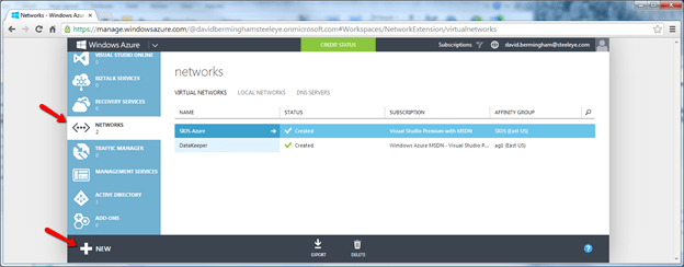
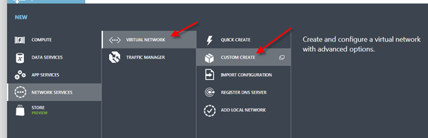
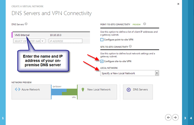
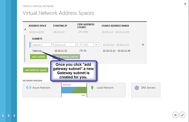
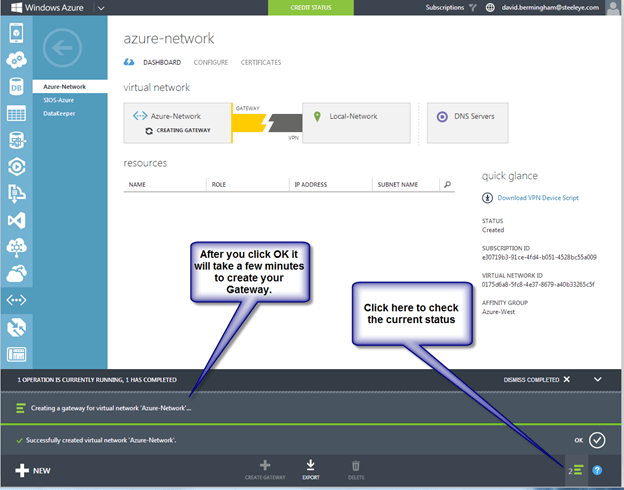
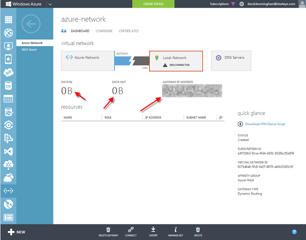
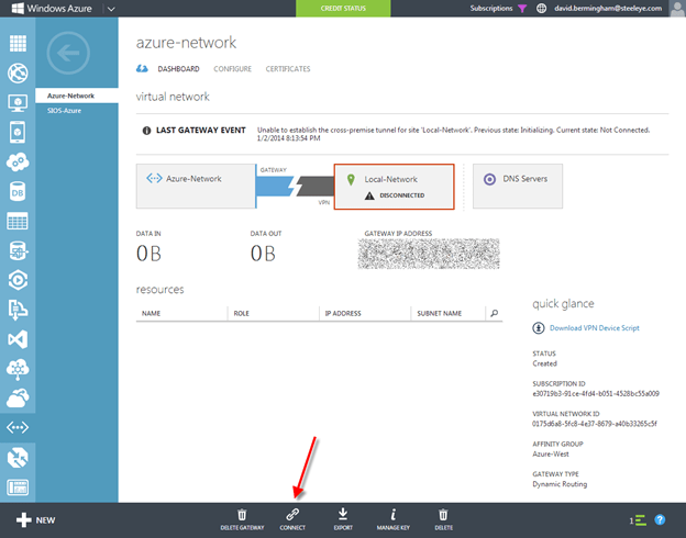
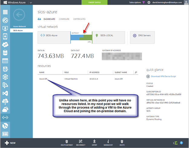
This post assumes you have created a Virtual Network in Azure and you have your first DC already provisioned in Azure. If you haven’t done that yet, you will want to go ahead and have a look at the first two posts on this topic.

The high levels steps which we will illustrate in this post are as follows:

  • Provision two Windows Server 2012 R2 Servers
  • Add the servers to the domain
  • Enable the Failover Clustering feature
  • Create the cluster
  • Create a replicated volume cluster resource with DataKeeper Cluster Edition
  • Install SQL 2014 Failover Cluster Instance

Provision two Windows Server 2012 R2 Servers

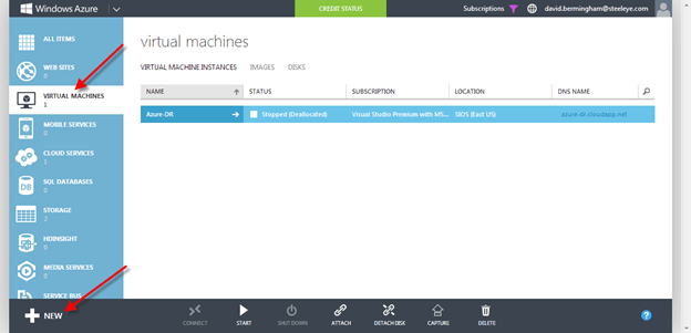
Click on the Virtual Machine tab in the left column and then click the New button in the bottom left corner.

Choose New Virtual Machine From Gallarey

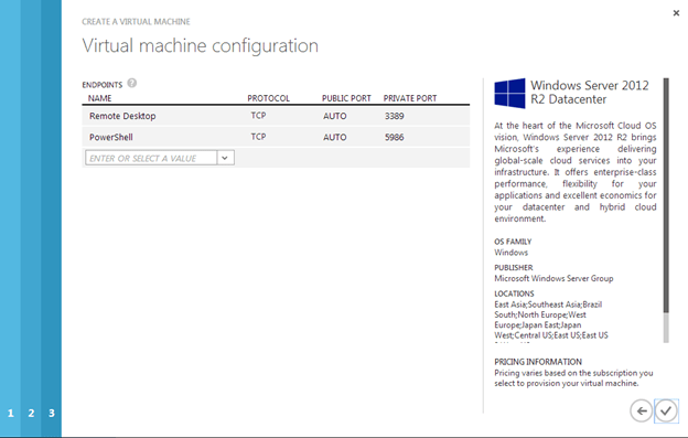
For our cluster we are going to choose Windows 2012 R2 Datacenter

Choose the latest Version Release Date, Name the VM and Size. The user name and password will be the local administrator account that you will use to log in to the VM to complete the configuration.

On this next page you will choose the following:

Cloud Service: I choose the same Cloud Service that I created when I provisioned my first VM. Cloud Service documentation says that it is used for load balancing, but I see no harm in putting all of the cluster VMs and DCs in the same Cloud Service for easier management. By choosing an existing Cloud Service my Virtual Network and Subnets are automatically selected for me.

Storage Account: I choose an existing Storage Account

Availability Set: This is EXTEMELY important. You want to make sure all of your VMs reside in the same Availability Set. By put putting all of your VMs in the same Availability Set you guarantee that the VMs all run in a different Fault Domain.

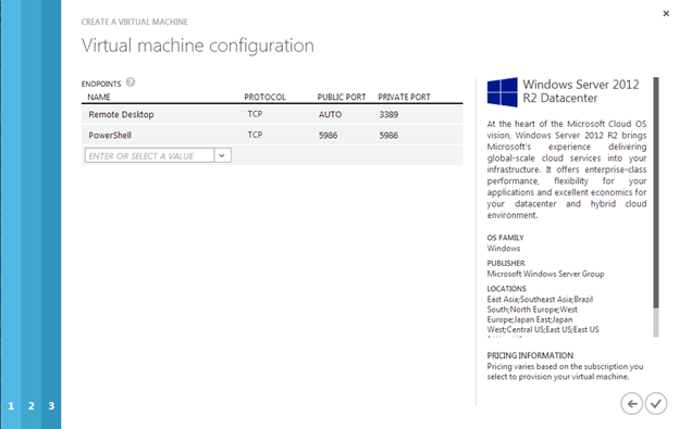
The last page shows the ports where this VM can be reached.

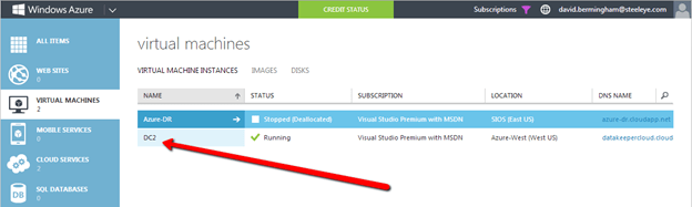
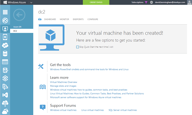
Once the VM is created you will see it as a new VM in the Azure Portal

The next step is to add additional storage to the VM. Azure best practices would have you put your databases and log files on the same volume, otherwise you must disable the Geo-replication feature that is enabled by default. The following article describes this issue in more detail: http://msdn.microsoft.com/en-us/library/jj870962.aspx#BKMK_GEO

To add additional storage to your VM, click on the VM and then Dashboard to get to the VMs dashboard. Once there, click on Attach.

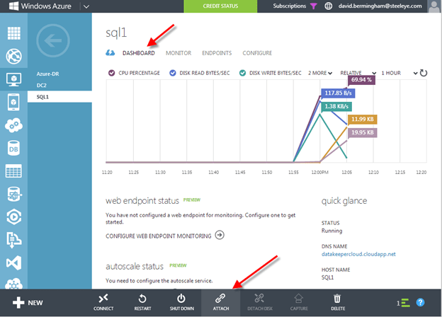
There are lots of things to consider when considering storage options for SQL Server. The safest and easiest method is the one we will use in this post. We will use a single volume for our data and log files and have caching disabled. You will want to read this article for the latest information on SQL Server Performance Considerations and best practices for Azure.

http://msdn.microsoft.com/en-us/library/windowsazure/dn133149.aspx

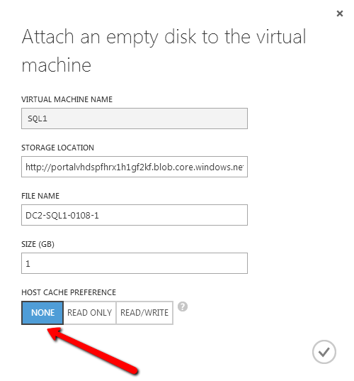
After you add this additional volume, you will need to open each VM and use Disk Management to initialize and format the volumes. For the purpose of this demo we will format this volume as the “F:\” drive.

You now have one VM called SQL1. You will want to complete the same process as described about to provision another VM and call it SQL2, making sure you put it in the same Cloud Service, Availability Set and Storage Account. Also make sure to attach another volume to SQL2 just as you have done for SQL1 and format it as the F:\ drive.

When you have finished provisioning both VMs we will move forward to the next step, adding them to the domain.

Add them to domain

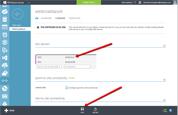
Adding SQL1 and SQL2 to the domain is a simple process. Assuming you have been following along with my previous posts, you have already created your domain and have a DC called DC2 provisioned in the same Cloud Service as SQ1 and SQL2. Adding them to the domain is as simple as connecting to the VMs and adding the VMs to the domain just as you would for in a regular on-premise network. If you configured the Virtual Network properly the new VMs should boot with an IP address assigned by DHCP which specifies the local DC2 and the domain controller.

Click Connect to open an RDP session to SQL1 and SQL2

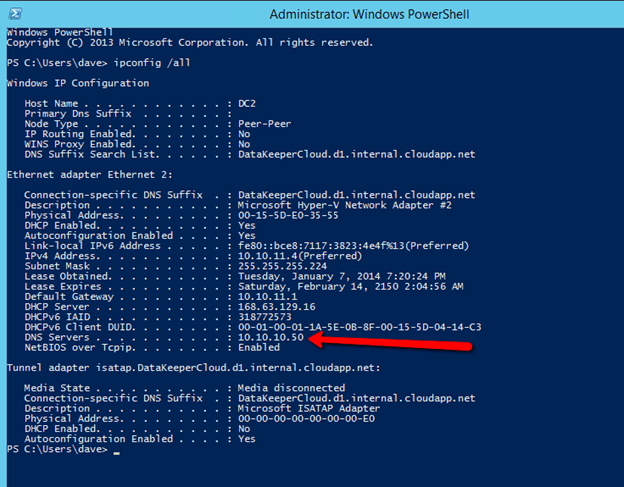
IPconfig /all shows the current IP configuration. Windows Azure requires that you leave the addresses set to use the DHCP server, however the IP address will not change for the life of the VM. You should notice that your DNS server is set to the local DNS server that you created in the previous article previously.

Add SQL1 and SQL2 to the domain and continue with the next steps.

Enable Failover Clustering feature

On both SQL1 and SQL2 you will enable the Failover Clustering feature

Create Cluster

If you are familiar with clustering then the following steps should be very familiar to you with just a few exceptions, so pay close attention to avoid problems that are specific to deploying clusters in Windows Azure.

We will start by creating a single node cluster, this will allow us to make the necessary adjustment to the cluster name resource before we add the second node to the cluster. Use Failover Cluster Manager and start by choosing Create Cluster. Add SQL1 to the selected servers and click Next.

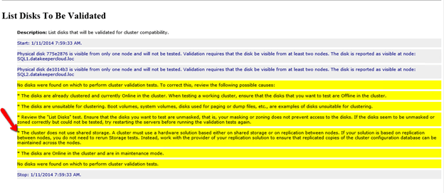
In order for us to install SQL Server 2014 into the cluster at the later steps, we will need to complete cluster Validation

Step through the rest of the cluster creation process as shown below. We will call this cluster SQLCLUSTER, which is simply the name we use to manage the cluster. This is NOT the name that you client applications will eventually connect to.

Once the cluster create process completes, you will notice that the cluster name resource fails to come online, this is expected.

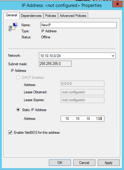
The name resource failed to come online because the IP resource failed to come online. The IP address failed to come online because the address that the DHCP server handed out is the same as the physical address of the server, in this case 10.10.11.5, so there is a duplicate IP address conflict.

In order to fix this, we will need to go into the properties of the IP Address resource and change the address to another address in the same subnet that is not currently in use. I would select an address that is at the higher end of the subnet range in order to reduce the possibility that in the future you might deploy a new VM and Azure will hand out that cluster IP address, causing an IP address conflict. In order to eliminate this possibility, Microsoft will have to allow us more control over the DHCP address pool. For now, the only way to completely eliminate that possibility is to create a new subnet in the Virtual Private Network for any new VMs that you might deploy later, so only this cluster resides in this subnet. If you DO plan to deploy more VMs in this subnet, you might as well deploy them all at the same time so you know which IP addresses they will use, that way you can use whatever IP addresses are left of for the cluster(s).

To change the IP address, choose the Properties of the IP Address cluster resource and specify the new address.

Once the address is changed, right click on the Cluster Name resource and tell it to come online.

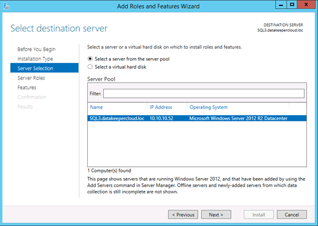
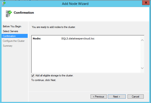
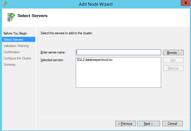
We are now ready to add the the second node to the cluster. In the Failover Cluster Manager, select Add Node

Browse out to your second node and click Add.

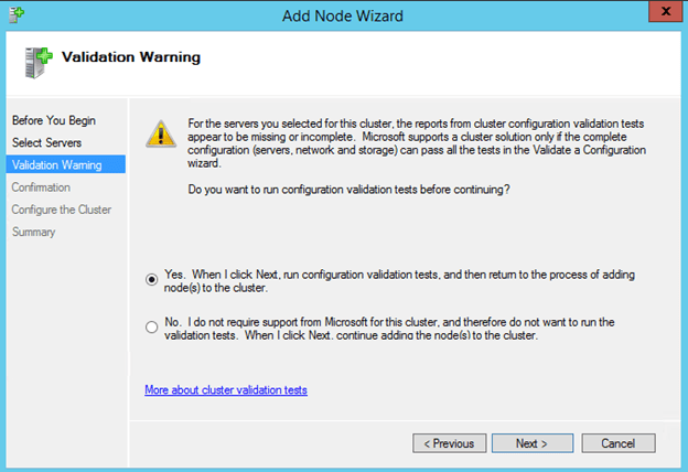
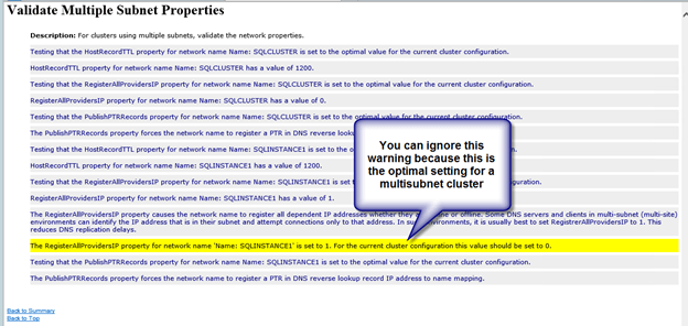
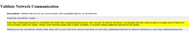
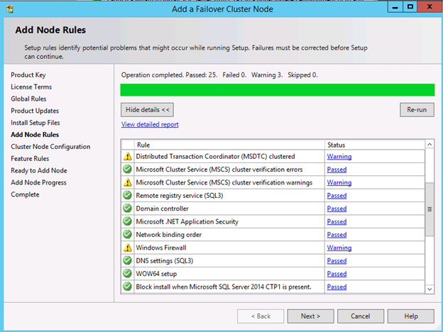
Run all the validation tests once again.

When you click finish, you will see that the node was added successfully, but because there is no shared storage in Azure, no disk witness for the quorum could be created. We will fix that next.

We now need to add a File Share Witness to our cluster to ensure the quorum requirements for two node cluster are satisfied. The file share witness will be configured on the DC2 server, the domain controller that is also running in the Azure Cloud.

Open up a RDP session to the domain controller in your Azure Private Cloud

Connect to your domain controller and create a file share called “Quorum”. You will need to give the Cluster Computer Name Object (which we called SQLCluster in this example) read/write permissions at both the Share level and Security (NTFS) level. If you are not familiar with creating a file share witness, you may want to review my previous post for more detail.

Once the file share witness folder is created on the domain controller, we need to add the witness in the cluster configuration using the Failover Cluster Manager on SQL1

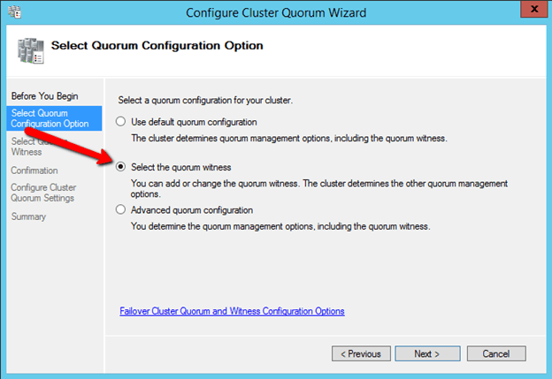
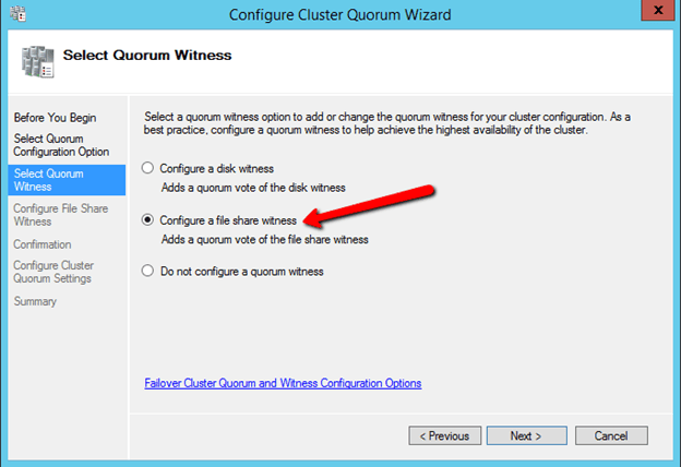
The File Share Witness should now be configured as shown below.

Create Replicated Volume Cluster Resource with DataKeeper Cluster Edition

A traditional failover cluster requires a shared storage device, like a SAN. The Azure IaaS cloud does not offer a storage solution that is capable of being used as a cluster disk, so we will use the 3rd party data replication solution called DataKeeper Cluster Edition which will allow us to create a replicate volume resource which can be used in place of a shared disk. A 14-day trial license is generally available for testing upon request.

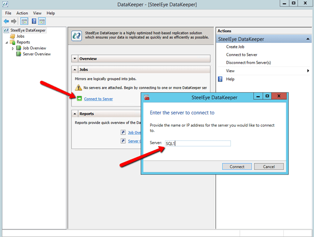
Once you download DataKeeper, install it and license it on both SQL1 and SQL2 and reboot the servers. Once the servers reboot, connect to SQL1, launch the DataKeeper UI and complete the steps below.
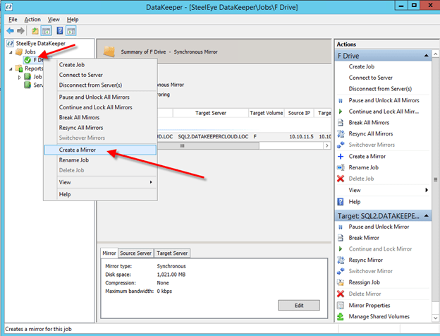
Connect” to both SQL1 and SQL2

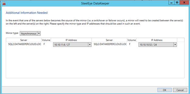
Now click on “Create Job” and follow the steps illustrated below to create the mirror and DataKeeper Volume cluster resource.

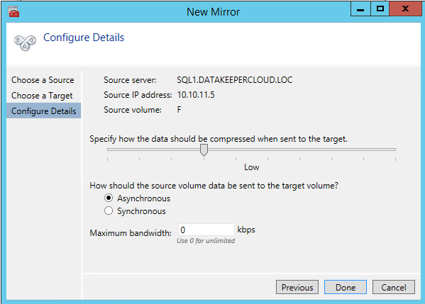
Choose the source of the mirror. When you choose the IP Address for the source and target, be sure to choose IP address of the server itself, DO NOT CHOOSE THE CLUSTER IP ADDRESS!

For this implementation where both nodes are in the Azure Cloud, choose synchronous replication with no compression, as shown below.

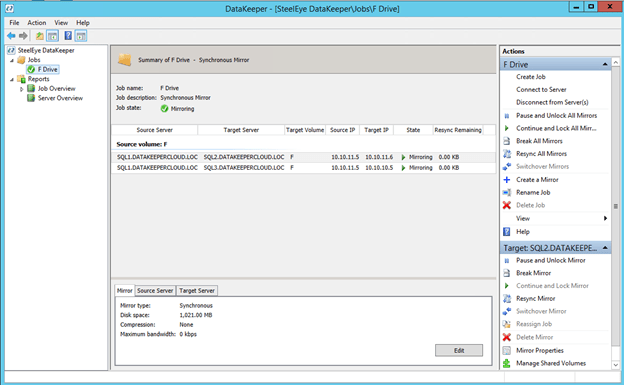
Click Done and you will be asked if you want to register this mirror in Windows Server Failover Clustering. Click Yes.

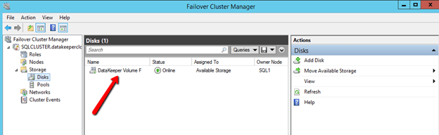
You will now see there is DataKeeper Volume Resource in Available Storage when you open the Windows Server Failover Cluster GUI

You are now ready to install SQL Server into the cluster.

Install SQL 2014 Failover Cluster Instance

To start the SQL Server 2014 cluster installation, you must download the SQL 2014 ISO to SQL1 and SQL2. You can use SQL Server 2014 Standard Edition for a simple two node cluster. If you want to extend this cluster to a 3rd site for disaster recovery as we will discuss in the next post, then you will need the Enterprise Edition because the Standard Edition only supports a 2-node cluster. If you are only looking for a simple two node solution than SQL Server Standard Edition can be a much more economical solution.

Once SQL Server 2014 is downloaded to the servers, mount the ISO and run the setup. The option that we want is to open is in the Advanced tab. Open the Advanced tab and run the “Advanced cluster preparation“. My good friend and fellow Cluster MVP, Robert Smit, told me about using the Advanced option. Basically, the Advanced option lets you split the install into two different processes, preparation and completion. Many things can go wrong with cluster installations, usually related to active directory and privileges. If you use the standard install method you may wait 20 minutes or longer for the installation to complete, only to find out that at the last minute the cluster was unable to register the CNO in active directory and the whole installation fails. Not only did the whole installation fail, now you may have a partially installed SQL Server cluster and you have a mess to clean up. By using the Advanced method you are able to minimize the risk by putting the risky section just at the end during cluster completion. If cluster completion fails, you simply need to diagnose the problem and re-run just the cluster completion process once again.

If you really want to save some time, check out Robert’s article on installing SQL Cluster with a configuration file, it is pretty easy to do and saves a bunch of time if you are doing multiple installations. However, for our purposes we will walk through the SQL install with the GUI as shown below.

For demo purposes, I just used the administrator account for each of the services. In production you will want to create separate accounts for each service as a best practice.

Once the install completes it looks like this.

Now we are ready to move forward with part two of the installation, Advanced Cluster Completion.

Give the SQL instance a name. This is the name the clients will connect to. In this case I called it SQLINSTANCE1.

This is where the magic happens. If you configured the mirror in DataKeeper as described earlier, you will see the DataKeeper Volume listed here as an Available Shared Disk, when actually it is simply a replicated volume pair.

One the Cluster Network Configuration page, it is important to choose IPv4 and to specify an address that is not in use in your subnet. As stated before, this address should be at the higher end of the DHCP range to help minimize the risk that Azure will assign that address to another VM in the future. I highly suggest that you have a subnet that is dedicated to your cluster to avoid possible conflicts until Windows Azure offers us greater control over the IP addresses and DHCP ranges. Later, after the cluster is created, you will need to delete this client access point and add the client access point as described in http://blogs.msdn.com/b/sqlalwayson/archive/2013/08/06/availability-group-listener-in-windows-azure-now-supported-and-scripts-for-cloud-only-configuration.aspx. I will publish a blog post in the future that describes this process in detail.

On this page make sure you Click Add Current User, or specify the accounts you wish to use to administer SQL Server.

Starting with SQL Server 2012, tempdb no longer needs to be part of the SQL Server Cluster. If you move the tempdb to a non-replicated volume, you will need to make sure that directory structure exists on each node. To change the location of the tempdb, click on the Data Directories tab and change the location where the tempdb is located.

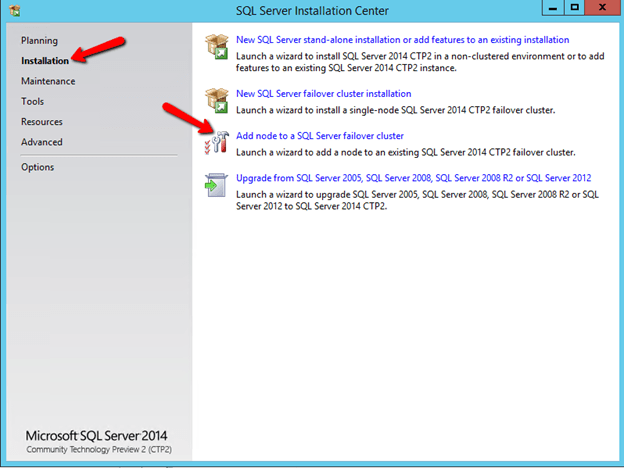
When the installation completes on SQL1, it is time to run the SQL installer on SQL2 and add the second node to the cluster. Run the Setup on SQL2 and choose Add node to a SQL Server failover cluster.

After the installation completes, you now have a fully functional SQL Server AlwaysOn Failover Cluster Instance (FCI) running on the Azure Cloud. Each instance is in a different Fault Domain providing a high level of resiliency. Be sure to replace the client access point with a client access point as described in my post…

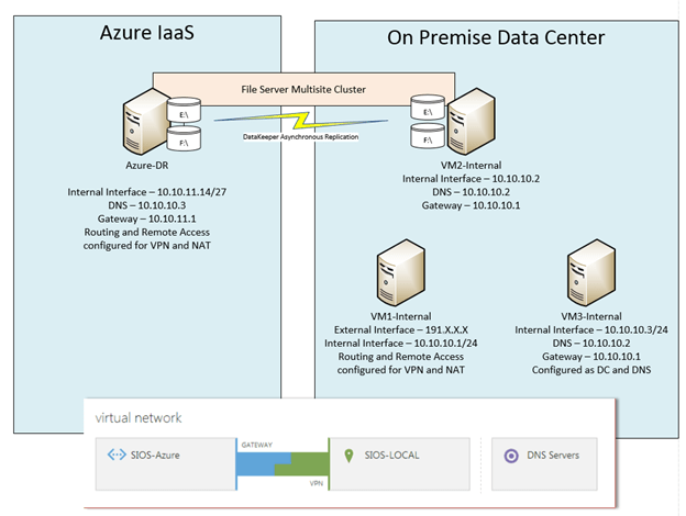
In the next post in this series I will show you how to extend this two node cluster to a third node for a multi-site cluster. This third-node will be located in my on-premise data center, which will give us the ultimate in both high availability and disaster recovery.

Creating a SQL Server 2014 AlwaysOn Failover Cluster (FCI) Instance in Windows Azure IaaS #Azure #Cloud

Extending Your Datacenter to the Azure Cloud #Azure

In part 1 of my series on using Windows Azure as a disaster recovery site, I explained how to create a site-to-site VPN using Windows Server 2012 R2 Routing and Remote Access (RRAS). Now that the two sites are connected, I’m going to walk you through the steps required deploy your first VM in the Windows Azure IaaS Cloud and add it to your on-premise network as a Domain Controller. I will assume you have already done the following:

  • Have a functioning on-premise Active Directory
  • Have complete the steps to create a site-to-site VPN connecting your on-premise datacenter to the Azure Cloud and the VPN is connected.
  • Have created an Azure account and are familiar with logging in and basic management features

At this point we are ready to stat. Open the Windows Azure Portal. You should minimally see the Virtual Network the we previously created listed when you select the “All Items” category on the left.

To provision your first VM, click on the “Virtual Machines” in the left hand navigation pane and click “+New” in the bottom left hand corner.

For our purposes, we are going to create a new virtual machine from the gallery.

We will use the Windows Server 2012 R2 Datacenter Image.

Pick your machine size, username and password.

The next step has you create a “Cloud Service”, “Storage Account” and Availability Set. It also asks you where to place the VM. We will choose the Virtual Network that you previously created when you created your site-to-site VPN. We will create a new Cloud Service and Storage Account. The rest of the VMs we will create later will make use of the different accounts we create this first time through.

The final page lists the ports where you can administer this VM, but I’ll show you an easy way to RDP to it in just a moment.

Once the VM is provisioned it should look something like this.

If you click on the VM’s name you will be taking to the VM’s welcome screen where you can learn more about managing the VM

Click on Dashboard, this will give you some detail information about your VM. From here you will be able to click on the Connect button and launch an RDP session to connect to the running VM

Using the username and password you specified when you provisioned the VM, use the RDP session that opens when you click Connect to log in to the provisioned VM. Once connected, you will notice that the VM has a single NIC and it is configured to use DHCP. This is expected and DHCP is required. The VM will maintain the same internal IP address throughout the life of the VM through a DHCP reservation. Static IP addresses are NOT support, even though it may appear to work for a while should you change it to a static IP.

Also notice that if you configured you Virtual Network as I described in my first post, the DNS server should point to the DC/DNS Server that resides in your onsite network. This will ensure that we are able to add this server to the on-premise domain in the next step.

Assuming your VPN is connected to the Gateway as shown below, you should be able to ping the DNS server on the other side of the VPN.

Ping the DNS server to verify network communication between the Azure Cloud and your on-premise network.

At this point you are able to add this server as a second Domain Controller to your domain, just as you would any other typical domain controller. I’m going to assume you know to add a Domain Controller to an Existing Domain and are familiar with other best practices when it comes to AD design and deployment.

The last step I recommend you update your Azure Virtual Private Network to specify this new DC as the Primary DNS Server and use the other on-premise DC as your secondary domain controller.

Click on Networks, then the name of the Virtual Private Network you want to edit.

Add the new DNS server to the list and click Save

From this point on when you configure servers in this Virtual Private Network, the VMs will be automatically configure with two DNS servers.

In Part 3 of my series on configuring Windows Azure for High Availability and Disaster Recovery we will look at deploying a highly available SQL Server Failover Cluster Instance in the Windows Azure Cloud using the host based replication solution call DataKeeper Cluster Edition.

Extending Your Datacenter to the Azure Cloud #Azure

How to Create a Site-to-Site VPN Tunnel to the Windows Azure Cloud Using a Window Server 2012 R2 Routing and Remote Access (RRAS) Server

Not long ago I set out to build a multisite SQL Server cluster where one my nodes resides in my local data center and the other node resides in Microsoft’s Infrastructure as a Service (IaaS) offering, the Windows Azure Cloud. The Azure Cloud has an offering where you can deploy VMs and pay for just the resources you utilize, much like Amazon’s EC2. My goal was to create a proof of concept where I would use the Azure Cloud as an inexpensive disaster recovery site. My configuration is shown in Figure 1.

1. An example of the simple DR configuration I used in my POC

My on premise VMs are used as follows:

  • VM1-internal – Routing and Remote Access Server for NAT and VPN connectivity to the Azure Cloud
  • VM2-internal – The primary node in my cluster
  • VM3-internal – My domain controller

For this POC I only deployed on server in the Azure cloud, Azure-DR. Azure-DR is the secondary node in my cluster. If this were an actual production site, I certainly would also want to deploy another domain controller in the Azure cloud to ensure that my Active Directory was available in the DR site. Your actual DR configuration will vary greatly depending upon your needs. I will use the server name depicted in my illustration as I describe the configuration steps below.

The scope of this post

For the purpose of this post, I am going to focus on what you need to do to get to the point where you have configured your virtual network in Azure and you create a site to site VPN connection to your primary data center. My next article will discuss the steps required to actually create a multisite cluster for disaster recovery. As with most cloud related services, the interfaces and options tend to change rapidly; the screen shots and directions you see below are relevant as of January 2nd, 2014. Your experience may vary, but these directions should get you pretty darn close. If you encounter difference, please send me a comment and what you did to make it work so other users can benefit from your experience.

Create your Local Network

I’m not going to walk you through this step-by-step, but essentially you should have a Windows Server 2012 R2 DC configured (VM3-internal) and two additional Windows Server 2012 R2 servers in the domain (VM1-internal and VM2-internal). Each server should use the DC server as their primary DNS server and on VM2-internal and VM3-internal the gateway should be configured to point to VM1-internal, which will eventual be configure with Routing and Remote Access (RRAS). The RRAS (VM1-internal) should be dual homed, with one NIC connected to the internal network and one NIC connected directly to the Public network. Generally this will be the biggest obstacle in deploying this in your lab, as you must have a spare public IP address that you can use for your RRAS server. This configuration will not work if your RRAS server sits behind a NAT’s firewall, it must be directly connected to the internet. The RRAS Server should be configured with just the IP address, subnet mask and DNS server, no gateway should be defined. DO NOT enable Routing and Remote Access, this will be done automatically via a script at a later step.

Create a Virtual Network

Log in to the Windows Azure Management Portal and create a new Virtual Network following the steps illustrated below.


When you click the check box you should now see the new virtual network you just created.

Create the Gateway

Once the virtual network is created, you will need to create the Gateway. From the Dashboard of the newly created virtual network, you will be able to create a Gateway as shown below. As of April 25th, 2013, Static Routing with RRAS is not supported in the Azure VPN connection, so be sure to choose Dynamic Routing.

It could take 30 minutes or longer before your gateway is finished being created, be patient…

Once the gateway is finished creating, you will see your Gateway IP Address and the amount of Data In and Data Out as shown below.

Configure your local RRAS Server

At this point you are ready to configure your on-premise RRAS Server (VM1-internal) to create a site-to-site VPN to the Gateway that you just created. Microsoft has made this very easy, so don’t worry if networking and configuring VPNs are not your specialty. You will just need click on “Download VPN Device Script” and run it on your RRAS server. Microsoft also supports a bunch of Juniper and Cisco VPN routers as well, so if you want to move to a hardware based VPN device in the future you can always come back and download the configuration script specific to your device.

Choose Microsoft Corporation as the Vendor, RRAS as the Platform and Windows Server 2012 as the Operating System and click the checkbox to download the Powershell script. In my case, this same script worked just fine when run on Windows Server 2012 R2.

As of the date of this writing, it seems as if Microsoft has made the script creation process even more intelligent than it was just last month. The script that it just created for me was pre-populated with all the information required; I did not have to edit anything at all.

At this point, all you need to do is copy the script file on to your RRAS Server (VM1-internal) and save it as a .ps1 and run the PowerShell script. This script will install Routing and Remote Access and configure the Site-to-Site VPN to connect to the Windows Azure Virtual Network you just created. Once you have finished with the RRAS installation go back to the Azure Portal and click Connect to complete the VPN site-to-site connection.

When connected, the Azure Portal should look something like the following.

Enable NAT on the RRAS Server

The final step I had to take to have a usable network was to enable NAT on my RRAS Server. Without having NAT enabled none of my servers could reach the internet. The basic steps for enabling NAT on RRAS are as follows:

  • Open the Routing and Remote Access MMC
  • Expand IPv4, right-click General, and then click New Routing Protocol.
  • In Routing protocols, click NAT, and then click OK.
  • Right-click NAT, and then click New Interface.
  • Select the interface that connects to your private intranet, and then click OK.
  • Select Private interface connected to private network, and then click OK.
  • Right-click NAT, and then click New Interface again.
  • Select the interface that connects to the public Internet, and then click OK.
  • Select both Public interface connected to the Internet and Enable NAT on this interface, and then click OK.

Now What?

The fun can now begin. In my next post I will walk you through the process of provisioning a Windows VM in Azure and joining it to your on-premise domain.

How to Create a Site-to-Site VPN Tunnel to the Windows Azure Cloud Using a Window Server 2012 R2 Routing and Remote Access (RRAS) Server