So you have built a SQL Server Failover Cluster Instance (FCI), or maybe an SAP ASCS/ERS cluster in Azure. Each node of the cluster resides in a different Availability Zone (AZ), or maybe you have strict latency requirements and are using Placement Proximity Groups (PPG) and your nodes all reside in the same Availability Set. Regardless of the scenario, you now have a much higher level of availability for your business critical application than if you were just running a single instance.
Now that you have high availability (HA) covered, what are you going to do for disaster recovery? Regional disasters that take out multiple AZs are rare, but as recent history has shown us, Mother Nature can really pack a punch. You want to be prepared should an entire region go offline.
Azure Site Recovery (ASR) is Microsoft’s disaster recovery-as-a-service (DRaaS) offering that allows you to replicate entire VMs from one region to another. It can also replicate virtual machines and physical servers from on-prem into Azure, but for the purpose of this blog post we will focus on the Azure Region-to-Region DR capabilities.
Setting up ASR
We are going to assume you have already built your cluster using SIOS DataKeeper. If not, here are some pointers to help get you started.
We are also going to assume you are familiar with Azure Site Recovery. Instead of yet another guide on setting up ASR, I suggest you read the latest documentation from Microsoft. This article will focus instead on some things you may not have considered and the specific steps required to fix your cluster after a failover to a different subnet.
Paired Regions
Before you start down the DR path, you should be aware of the concept of Azure Paired Regions. Every Region in Azure has a preferred DR Region. If you want to learn more about Paired Regions, the documentation provides a great background. There are some really good benefits of using your paired region, but it’s really up to you to decide on what region you want to use to host your DR site.
Cloud Witness Location
When you originally built your cluster you had to choose a witness type for your quorum. You may have selected a File Share Witness or a Cloud Witness. Typically either of those witness types should reside in an AZ that is separate from your cluster nodes.
However, when you consider that, in the event of a disaster, your entire cluster will be running in your DR region, there is a better option. You should use a cloud witness, and place it in your DR region. By placing your cloud witness in your DR region, you provide resiliency not only for local AZ failures, but it also protects you should the entire region fail and you have to use ASR to recover your cluster in the DR region. Through the magic of Dynamic Quorum and Dynamic Witness, you can be sure that even if your DR region goes offline temporarily, it will not impact your production cluster.
Multi-VM Consistency
When using ASR to replicate a cluster, it is important to enable Multi-VM Consistency to ensure that each cluster node’s recovery point is from the same point in time. That ensures that the DataKeeper block level replication occurring between the VMs will be able to continue after recovery without requiring a complete resync.
Crash Consistent Recovery Points
Application consistent recovery points are not supported in replicated clusters. When configuring the ASR replication options do not enable application consistent recovery points.
Keep IP Address After Failover?
When using ASR to replicate to your DR site there is a way to keep the IP address of the VMs the same. Microsoft described it in the article entitled Retain IP addresses during failover. If you can keep the IP address the same after failover it will simplify the recovery process since you won’t have to fix any cluster IP addresses or DataKeeper mirror endpoints, which are based on IP addresses.
However, in my experience, I have never seen anyone actually follow the guidance above, so recovering a cluster in a different subnet will require a few additional steps after recovery before you can bring the cluster online.
Your First Failover Attempt
Recovery Plan
Because you are using Multi-VM Consistency, you have to failover your VMs using a Recovery Plan. The documentation provides pretty straightforward guidance on how to do that. A Recovery Plan groups the VMs you want to recover together to ensure they all failover together. You can even add multiple groups of VMs to the same Recovery Plan to ensure that your entire infrastructure fails over in an orderly fashion.
A Recovery Plan can also launch post recovery scripts to help the failover complete the recovery successfully. The steps I describe below can all be scripted out as part of your Recovery Plan, thereby fully automating the complete recovery process. We will not be covering that process in this blog post, but Microsoft documents this process.
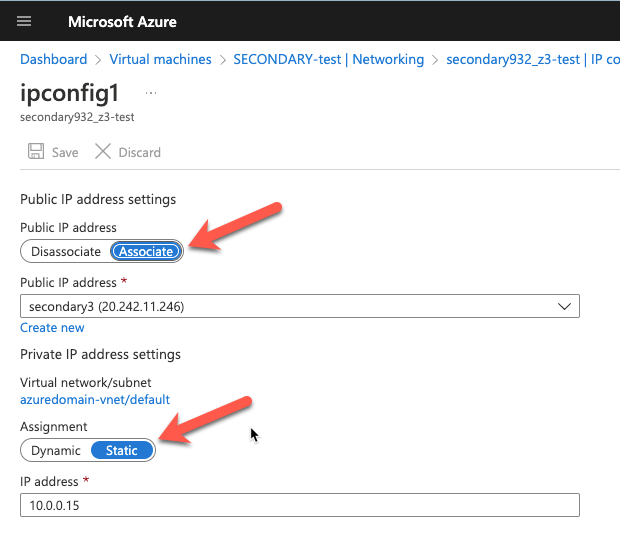
Static IP Addresses
As part of the recovery process you want to make sure the new VMs have static IP addresses. You will have to adjust the interface properties in the Azure Portal so that the VM always uses the same address. If you want to add a public IP address to the interface you should do so at this time as well.
Network Configuration
After the replicated VMs are successfully recovered in the DR site, the first thing you want to do is verify basic connectivity. Is the IP configuration correct? Are the instances using the right DNS server? Is name resolution functioning correctly? Can you ping the remote servers?
If there are any problems with network communications then the rest of the steps described below will be bound to fail. Don’t skip this step!
Load Balancer
As you probably know, clusters in Azure require you to configure a load balancer for client connectivity to work. The load balancer does not fail over as part of the Recovery Plan. You need to build a new load balancer based on the cluster that now resides in this new vNet. You can do this manually or script this as part of your Recovery Plan to happen automatically.
Network Security Groups
Running in this new subnet also means that you have to specify what Network Security Group you want to apply to these instances. You have to make sure the instances are able to communicate across the required ports. Again, you can do this manually, but it would be better to script this as part of your Recovery Plan.
Fix the IP Cluster Addresses
If you are unable to make the changes described earlier to recover your instances in the same subnet, you will have to complete the following steps to update your cluster IP addresses and the DataKeeper addresses for use in the new subnet.
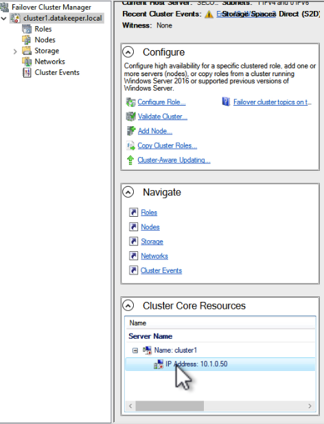
Every cluster has a core cluster IP address. What you will see if you launch the WSFC UI after a failover is that the cluster won’t be able to connect. This is because the IP address used by the cluster is not valid in the new subnet.
If you open the properties of that IP Address resource you can change the IP address to something that works in the new subnet. Make sure to update the Network and Subnet Mask as well.
Once you fix that IP Address you will have to do the same thing for any other cluster address that you use in your cluster resources.
Fix the DataKeeper Mirror Addresses
SIOS DataKeeper mirrors use IP addresses as mirror endpoints. These are stored in the mirror and mirror job. If you recover a DataKeeper based cluster in a different subnet, you will see that the mirror comes up in a Resync Pending state. You will also notice that the Source IP and the Target IP reflect the original subnet, not the subnet of the DR site.
Fixing this issue involves running a command from SIOS called CHANGEMIRRORENDPOINTS. The usage for CHANGEMIRRORENDPOINTS is as follows.
In our example, the command and output looked like this.
After the command runs, the DataKeeper GUI will be updated to reflect the new IP addresses as shown below. The mirror will also go to a mirroring state.
Conclusions
You have now successfully configured and tested disaster recovery of your business critical applications using a combination of SIOS DataKeeper for high availability and Azure Site Recovery for disaster recovery. If you have questions please leave me a comment or reach out to me on Twitter @daveberm
What makes this interesting is that you can now build shared storage based failover cluster instances that span Availability Zones (AZ). With cluster nodes residing in different AZs, users can now qualify for the 99.99% availability SLA. Prior to support for ZRS, Azure Shared Disks only supported Locally Redundant Storage (LRS), limiting cluster deployments to a single AZ, leaving users susceptible to outages should an AZ go offline.
There are however a few limitations to be aware of when deploying an Azure Shared Disk with ZRS.
Only supported with premium solid-state drives (SSD) and standard SSDs. Azure Ultra Disks are not supported.
Azure Shared Disks with ZRS are currently only available in West US 2, West Europe, North Europe, and France Central regions
Disk Caching, both read and write, are not supported with Premium SSD Azure Shared Disks
Disk bursting is not available for premium SSD
Azure Site Recovery support is not yet available.
Azure Backup is available through Azure Disk Backup only.
Only server-side encryption is supported, Azure Disk Encryption is not currently supported.
I also found an interesting note in the documentation.
“Except for more write latency, disks using ZRS are identical to disks using LRS, they have the same scale targets. Benchmark your disks to simulate the workload of your application and compare the latency between LRS and ZRS disks.”
While the documentation indicates that ZRS will incur some additional write latency, it is up to the user to determine just how much additional latency they can expect. A link to a disk benchmark document is provided to help guide you in your performance testing.
Following the guidance in the document, I used DiskSpd to measure the additional write latency you might experience. Of course results will vary with workload, disk type, instance size, etc.,but here are my results.
Locally Redundant Storage (LRS)
Zone Redundant Storage (ZRS)
Write IOPS
5099.82
4994.63
Average Latency
7.830
7.998
The DiskSpd test that I ran used the following parameters.
I wrote to a P30 disk with ZRS and a P30 with LRS attached to a Standard DS3 v2 (4 vcpus, 14 GiB memory) instance type. The shared ZRS P30 was also attached to an identical instance in a different AZ and added as shared storage to an empty cluster application.
A 2% overhead seems like a reasonable price to pay to have your data distributed synchronously across two AZs. However, I did wonder what would happen if you moved the clustered application to the remote node, effectively putting your disk in one AZ and your instance in a different AZ.
Here are the results.
Locally Redundant Storage (LRS)
Zone Redundant Storage (ZRS)
ZRS when writing from the remote AZ
Write IOPS
5099.82
4994.63
4079.72
Average Latency
7.830
7.998
9.800
In that scenario I measured a 25% write latency increase. If you experience a complete failure of an AZ, both the storage and the instance will failover to the secondary AZ and you shouldn’t experience this increase in latency at all. However, other failure scenarios that aren’t AZ wide could very well have your clustered application running in one AZ with your Azure Shared Disk running in a different AZ. In those scenarios you will want to move your clustered workload back to a node that resides in the same AZ as your storage as soon as possible to avoid the additional overhead.
Microsoft documents how to initiate a storage account failover to a different region when using GRS, but there is no way to manually initiate the failover of a storage account to a different AZ when using ZRS. You should monitor your failover cluster instance to ensure you are alerted any time a cluster workload moves to a different server and plan to move it back just as soon as it is safe to do so.
You can find yourself in this situation unexpectedly, but it will also certainly happen during planned maintenance of the clustered application servers when you do a rolling update. Awareness is the key to help you minimize the amount of time your storage is performing in a degraded state.
I hope in the future Microsoft allows users to initiate a manual failover of a ZRS disk the same as they do with GRS. The reason they added the feature to GRS was to put the power in the hands of the users in case automatic failover did not happen as expected. In the case of ZRS I could see people wanting to try to tie together storage and application, ensuring they are always running in the same AZ, similar to how host based replication solutions like SIOS DataKeeper do it.
When deploying business critical applications in the cloud you want to make sure they are highly available. The good news is that if you plan properly, you can achieve 99.99% (4-nines) of availability or more. However, calculating your true availability may not be as straightforward as it seems.
When considering availability you must consider the key components that make access to your application possible, which I’ll call the availability chain. Component of the availability chain are:
Compute
Network
Storage
Application
Dependent services
Your application is only as available as your weakest link, and your downtime increases exponentially with each additional link you add to the chain. Let’s examine each of the links.
Compute Availability
Each of the three major cloud service providers have some similarities. One thing in common across all three platforms is the service level agreements (SLA) they will commit to for compute.
The SLA for all three public cloud providers for VMs when you have two or more VMs configured across different availability zones is 99.99%. Keep in mind, this SLA only guarantees the remote accessibility of one of the VMs at any given time, it makes no promises as to the availability of the services or application(s) running inside the VM. If you deploy a single VM within a single datacenter, this SLA varies from “90% of each hour” (AWS) to 99.5% (Azure and GCP) or 99.9% (Azure single VM when using Premium SSD).
True high availability starts at 99.99%, so the first step is to ensure your application is available is to make sure the application is distributed across two or more VMs that span availability zones. With two VMs spread across two availability zones, giving you 99.99% availability of at least one of those VMs, you could theorize that if you had three VMs spread across three availability zones your availability would be even greater than 99.99%. Although the cloud providers’ SLA will never guarantee beyond 99.99% availability regardless of the number of availability zones in use, if you use pure statistics you might come to the conclusion that your availability could jump to as high as 99.999999% or 8-nines of availability, 26.30 milliseconds downtime per month.
1-(.0001*.0001) = .99999999
99.999999% availability with three availability zones?
Don’t go around quoting that number, but just keep in mind that it makes sense that if two availability zones can give you 99.99% availability, it stands to reason that three availability zones is going to give you something significantly more than 99.99% availability.
Compute is just one link in the availability chain. We still have to address network, storage and other dependent services, which all represent possible points of failure.
Network Availability
In order for your application to be available, every network hop between the client and the application and all the resources that the application depends on, must be available and working within tolerable latency ranges. You need to understand the network links between database servers, application servers, web servers and clients to know precisely where the network might fail. And remember, the more links in your availability chain the lower your overall availability will be.
Although network availability betweens VMs in the same vNet are covered under the standard compute SLA, there are other network services that you may be utilizing. Here are just a few examples of network services you could be utilizing which would impact overall application availability.
It seems pretty clear that Azure and Google are giving you a 99.9% SLA on block storage solutions. AWS doesn’t mention EBS specifically here. They only talk about VMs and measure their single instance VMs availability by the hour instead of by the month as the other cloud providers do. For sake of discussion, lets use the 99.9% availability guarantee that both Azure and GCP have published.
Building upon our previous example, let’s add some storage to the equation.
99.99% compute availability
99.99% load balancer availability
99.9% managed disk
.9999 * .9999 * .999 = .9988
99.88% availability = ~53 minutes of downtime per month.
53 minutes of downtime is a lot more than the 9 minutes of downtime we calculated in our previous example. What can we do to minimize the impact of the 99.9% storage availability? We have to build more redundancy in the storage!
Fortunately, we usually include storage redundancy when planning for application availability. For instance, when we stand up web servers, each web server will typically store data on the locally attached disk. When deploying domain controllers, Microsoft Active Directory takes care of replicating AD information across all the domain controllers. In the case of something like SQL Server, we leverage things Always On Availability Groups or SIOS DataKeeper to keep the data in sync across locally attached disks.
The more copies of the data we have distributed across different availability zones, the more likely we will be able to survive a failure.
For example, an application that stores its data across two different disks in different availability zones will benefit from the redundancy and instead of 99.9% availability it is more likely to achieve 99.9999% availability of the storage.
1 – (.001 * .001) = .999999
If we throw that into the previous equation the picture starts to look a little brighter.
.9999 * .9999 * .999999 = .9998
99.98% availability = ~9 minutes of downtime
By duplicating the data across multiple AZs, and therefore multiple disks, we have effectively mitigated the downtime associated with cloud storage.
Application and Dependent Services Availability
You’ve done all you can do to ensure compute, network, and storage availability. But what about the application itself? Some applications can scale out and provide redundancy by load balancing between multiple instances of the same application. Think of your typical web server farm where you may typically load balance web requests between five servers. If you lose one server the load balancer simply removes it from it’s rotation until it is once again responsive.
Other applications require a little more care and monitoring. Take SQL Server for instance. Typically Always On Availability Groups or Failover Cluster Instances are used to monitor database availability and take recovery actions should a database become unresponsive due to application or system level failures. While there is no published SLA for SQL Server availability solutions, it is commonly accepted that when configured properly for high availability, a SQL Server can provide 99.99% availability.
You may rely on other cloud based services, like hosted Active Directory, hosted DNS, microservices, or even the availability of the cloud portal itself should all be factored into your overall availability equation.
Summary
Application availability is the sum of all the moving parts. Skimping in just one area can exponentially impact the overall availability of your application. Take your time and investigate all the links in your availability chain for weakness including compute, network, storage, application and dependent services.
In general the numbers presented here are hopefully worst case scenarios and your actual availability should exceed the published SLAs. Do your homework and be wary of any service that can not guarantee 99.99% availability, the typical threshold of what is considered highly available.
Human error and security were not addressed in this article. You can make your application as highly available as possible, but if you have not taken steps to secure your application against external threats and stupid human mistakes then all bets are off when it comes to availability.
I recently helped someone build an iSCSI target server cluster in Azure and realized that I never wrote a step-by-step guide for that particular configuration. So to remedy that, here are the step-by-step instructions in case you need to do this yourself.
Pre-requisites
I’m going to assume you are fairly familiar with Azure and Windows Server, so I’m going to spare you some of the details. Let’s assume you have at least done the following as a pre-requisite
Provision two servers (SQL1, SQL2) each in a different Availability Zone (Availability Set is also possible, but Availability Zones have a better SLA)
Assign static IP addresses to them through the Azure portal
Joined the servers to an existing domain
Enabled the Failover Clustering feature and the iSCSI Target Server feature on both nodes
Add three Azure Premium Disk to each node. NOTE: this is optional, one disk is the minimum required. For increased IOPS we are going to stripe three Premium Azure Disks together in a storage pool and create a simple (RAID 0) virtual disk
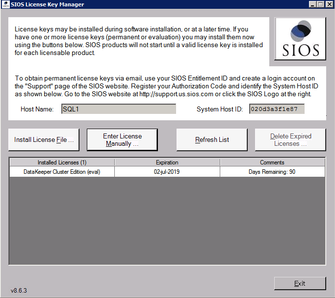
SIOS DataKeeper is going to be used to provided the replicated storage used in the cluster. If you need DataKeeper you can request a trial here.
Create local Storage Pool
Once again, this step is completely optional, but for increased IOPS we are going to stripe together three Azure Premium Disks into a single Storage Pool. You might be tempted to use Dynamic Disk and a spanned volume instead, but don’t do that! If you use dynamic disks you will find out that there is some general incompatibility that will prevent you from creating iSCSI targets later.
Don’t worry, creating a local Storage Pool is pretty straight forward if you are aware of the pitfalls you might encounter as described below. The official documentation can be found here.
Pitfall #1 – although the documentation says the minimum size for a volume to be used in a storage pool is 4 GB, I found that the P1 Premium Disk (4GB) was NOT recognized. So in my lab I used 16GB P3 Premium Disks.
Pitfall #2 – you HAVE to have at least three disks to create a Storage Pool.
Pitfall #3 – create your Storage Pool before you create your cluster. If you try to do it after you create your cluster you are going to wind up with a big mess as Microsoft tries to create a clustered storage pool for you. We are NOT going to create a clustered storage pool, so avoid that mess by creating your Storage Pool before you create the cluster. If you have to add a Storage Pool after the cluster is created you will first have to evict the node from the cluster, then create the Storage Pool.
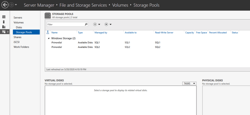
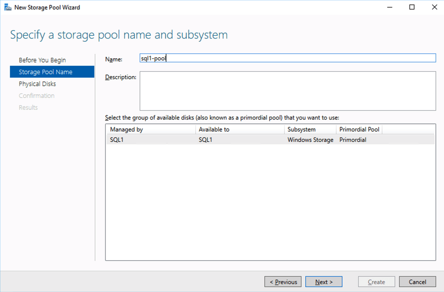
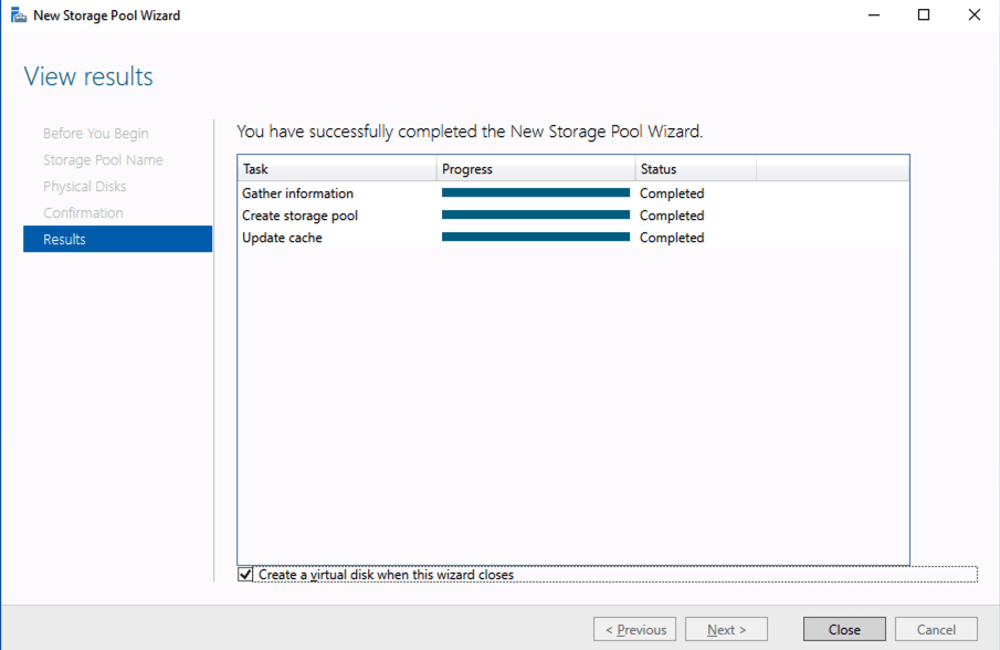
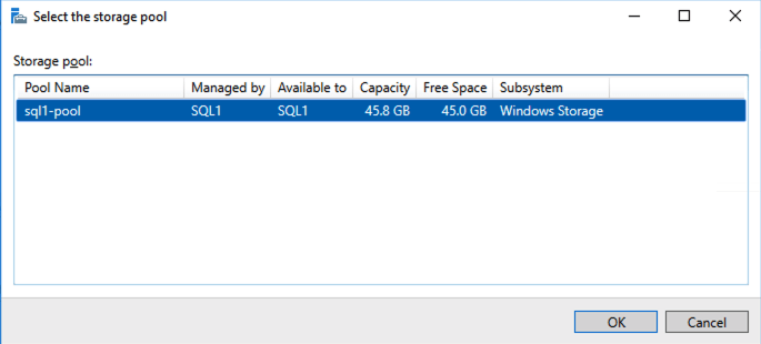
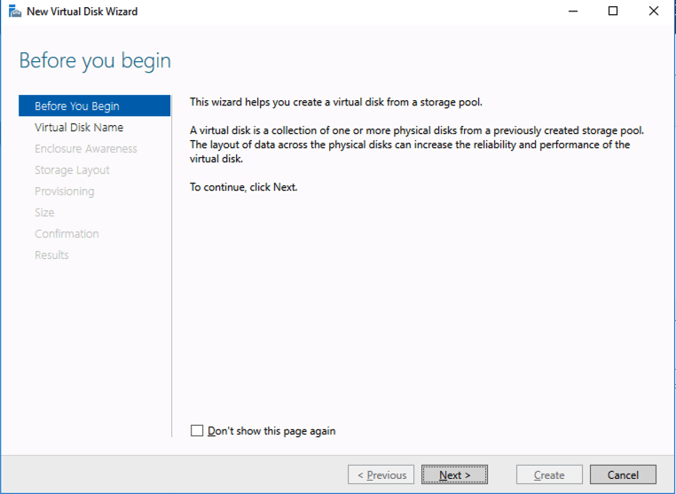
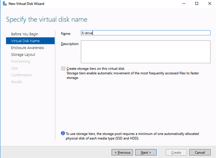
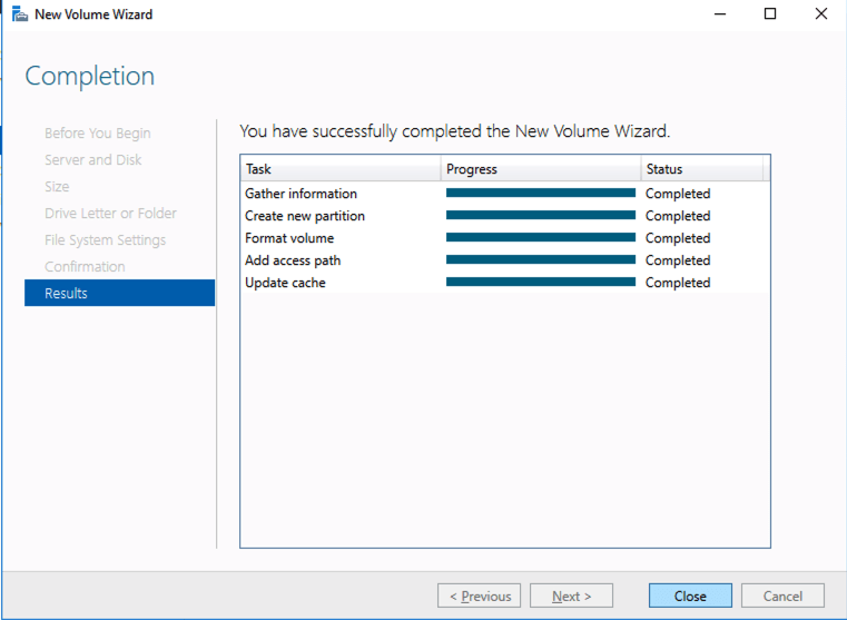
Based on the documentation found here, below are the screenshots that represent what you should see when you build your local Storage Pool on each of the two cluster nodes. Complete these steps on both servers BEFORE you build the cluster.
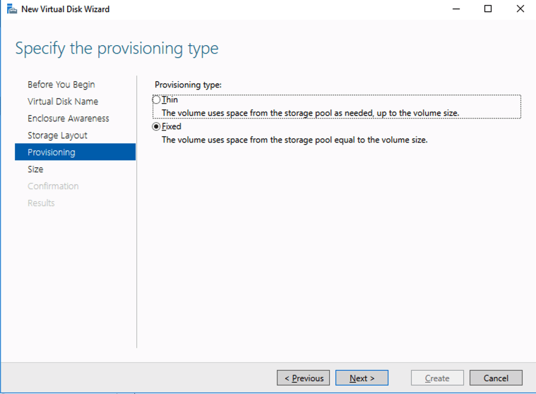
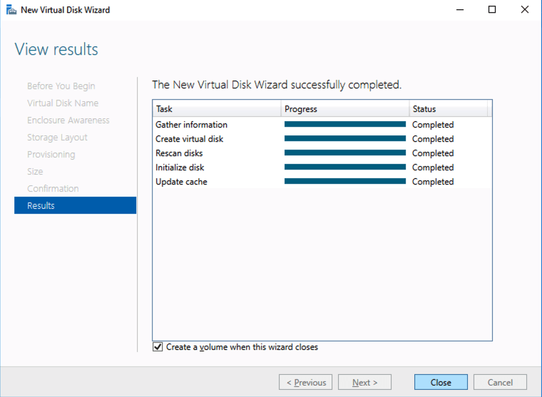
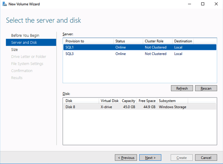
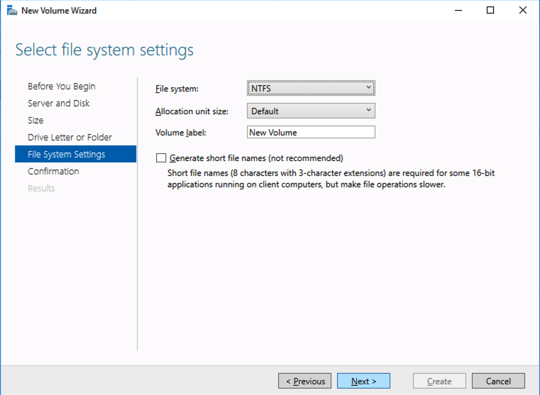
You should see the Primordial pool on both servers.Right-click and choose New Storage Pool…Choose Create a virtual disk when this wizard closesNotice here you could create storage tiers if you decided to use a combination of Standard, Premium and Ultra SSDFor best performance use Simple storage layout (RAID 0). Don’t be concerned about reliability since Azure Managed Disks have triple redundancy on the backend. Simple is required for optimal performance.For performance purposes use Fixed provisioning. You are already paying for the full Premium disk anyway, so no need not to use it all.Now you will have a 45 GB X drive on your first node. Repeat this entire process for the second node.
Create your Cluster
Now that each server each have their own 45 GB X drive, we are going to create the basic cluster. Creating a cluster in Azure is best done via Powershell so that we can specify a static IP address. If you do it through the GUI you will soon realize that Azure assigns your cluster IP a duplicate IP address that you will have to clean up, so don’t do that!
Here is an example Powershell code to create a new cluster.
PS C:\Users\dave.DATAKEEPER> New-Cluster -Name mycluster -NoStorage -StaticAddress 10.0.0.100 -Node sql1, sql2
WARNING: There were issues while creating the clustered role that may prevent it from starting. For more information view the report file below.
WARNING: Report file location: C:\windows\cluster\Reports\Create Cluster Wizard mycluster on 2020.05.20 At 16.54.45.htm

Name
----
mycluster
The warning in the report will tell you that there is no witness. Because there is no shared storage in this cluster you will have to create either a Cloud Witness or a File Share Witness. I’m not going to walk you through that process as it is pretty well documented at those links.
Don’t put this off, go ahead and create the witness now before you move to the next step!
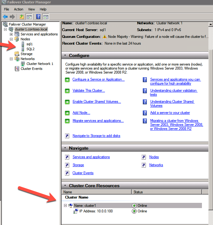
You now should have a basic 2-node cluster that looks something like this.
Configure a Load Balancer for the Cluster Core IP Address
Clusters in Azure are unique in that the Azure virtual network does not support gratuitous ARP. Don’t worry if you don’t know what that means, all you have to really know is that cluster IP addresses can’t be reached directly. Instead, you have to use an Azure Load Balancer, which redirects the client connection to the active cluster node.
There are two steps to getting a load balancer configured for a cluster in Azure. The first step is to create the load balancer. The second step is to update the cluster IP address so that it listens for the load balancer’s health probe and uses a 255.255.255.255 subnet mask which enables you to avoid IP address conflicts with the ILB.
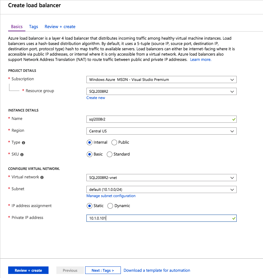
We will first create a load balancer for the cluster core IP address. Later we will edit the load balancer to also address the iSCSI cluster resource IP address that we will be created at the end of this document.
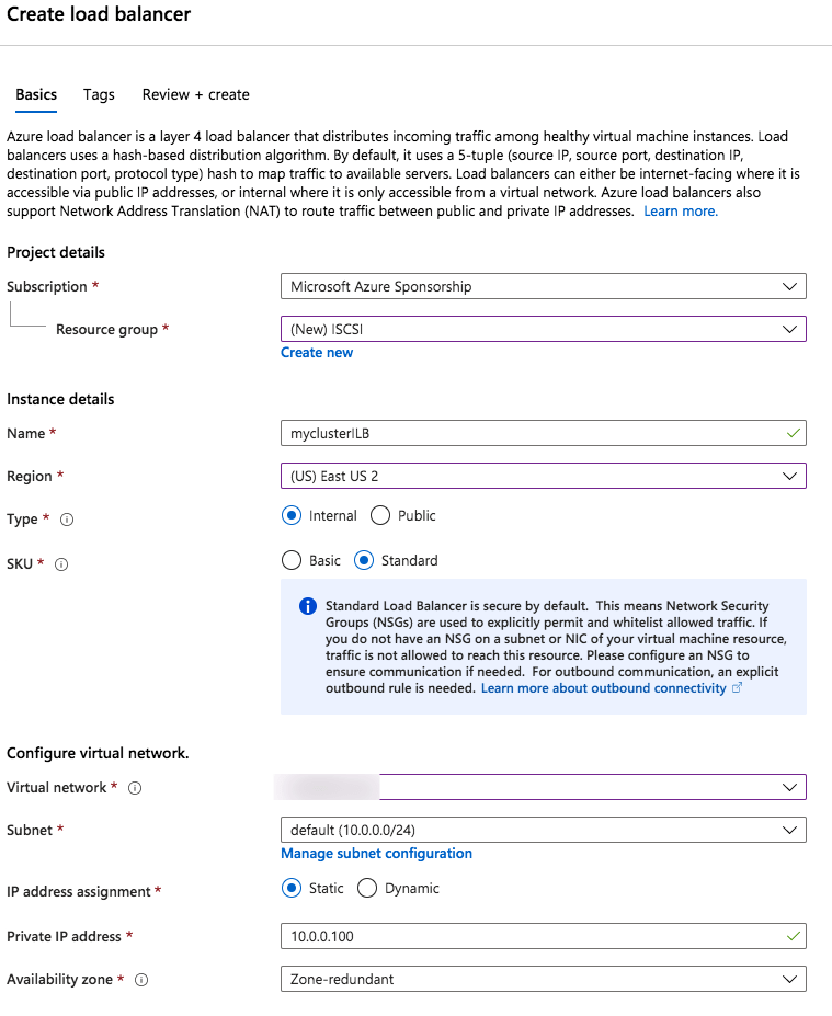
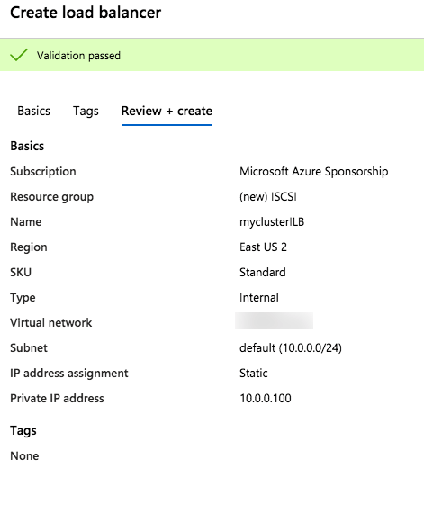
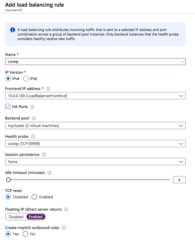
Step 1 – Create a Standard Load Balancer
Notice that the static IP address we are using is the same address that we used to create the core cluster IP resource.
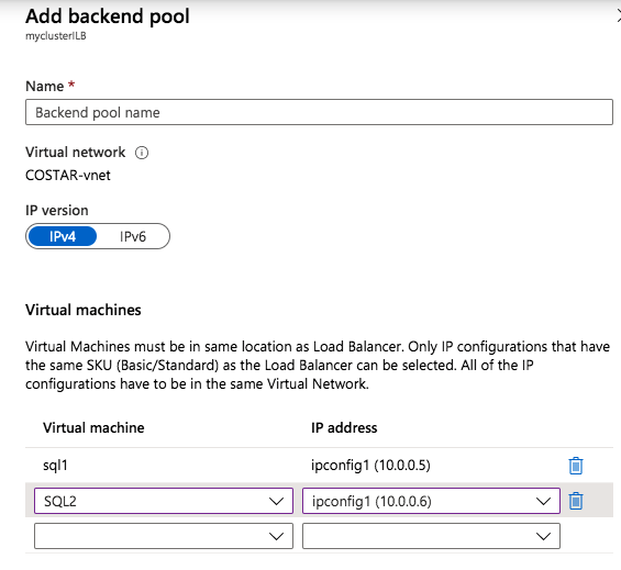
Once the load balancer is created you will edit the load balancer as shown below
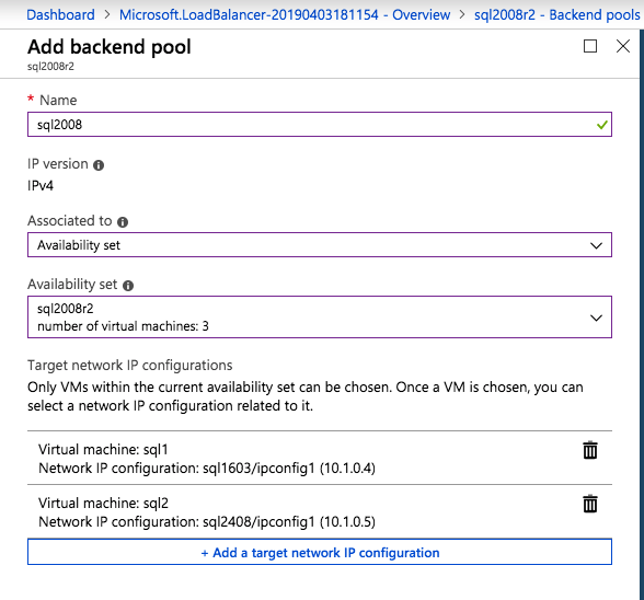
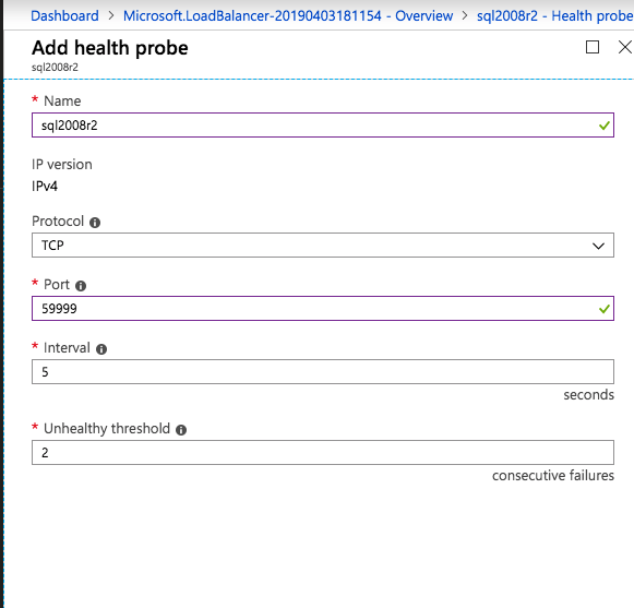
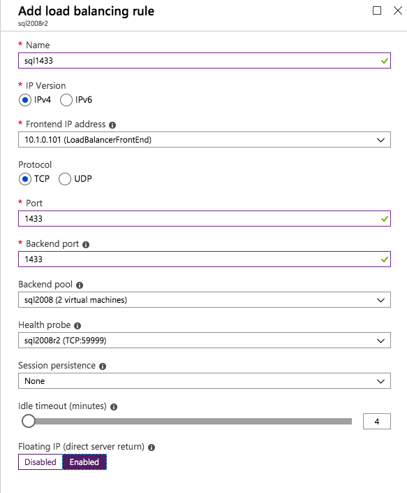
Add the two cluster nodes to the backend poolAdd a health probe. In this example we use 59999 as the port. Remember that port, we will need it in the next step.Create a new rue to redirect all HA ports, Make sure Floating IP is enabled.
Step 2 – Edit to cluster core IP address to work with the load balancer
As I mentioned earlier, there are two steps to getting the load balancer configured to work properly. Now that we have a load balancer, we have to run a Powershell script on one of the cluster nodes. The following is an example script that needs to be run on one of the cluster nodes.
The important thing about the script above, besides getting all the variables correct for your environment, is making sure the ProbePort is set to the same port you defined in your load balancer settings for this particular IP address. You will see later that we will create a 2nd health probe for the iSCSI cluster IP resource that will use a different port. The other important thing is making sure you leave the subnet set at 255.255.255.255. It may look wrong, but that is what it needs to be set to.
After you run it the output should look like this.
 PS C:\Users\dave.DATAKEEPER> $ClusterNetworkName = “Cluster Network 1”
$IPResourceName = “Cluster IP Address”
$ILBIP = “10.0.0.100”
Import-Module FailoverClusters
Get-ClusterResource $IPResourceName | Set-ClusterParameter -Multiple @{Address=$ILBIP;ProbePort=59999;SubnetMask="255.255.255.255";Network=$ClusterNetworkName;EnableDhcp=0}
WARNING: The properties were stored, but not all changes will take effect until Cluster IP Address is taken offline and then online again.
You will need to take the core cluster IP resource offline and bring it back online again before it will function properly with the load balancer.
Assuming you did everything right in creating your load balancer, your Server Manager on both servers should list your cluster as Online as shown below.
Check Server Manager on both cluster nodes. Your cluster should show as “Online” under Manageability.
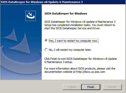
Install DataKeeper
I won’t go through all the steps here, but basically at this point you are ready to install SIOS DataKeeper on both cluster nodes. It’s a pretty simple setup, just run the setup and choose all the defaults. If you run into any problems with DataKeeper it is usually one of two things. The first issue is the service account. You need to make sure the account you are using to run the DataKeeper service is in the Local Administrators Group on each node.
The second issue is in regards to firewalls. Although the DataKeeper install will update the local Windows Firewall automatically, if your network is locked down you will need to make sure the cluster nodes can communicate with each other across the required DataKeeper ports. In addition, you need to make sure the ILB health probe can reach your servers.
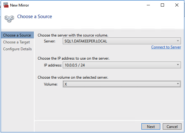
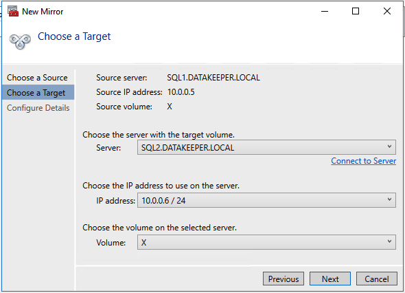
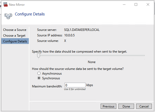
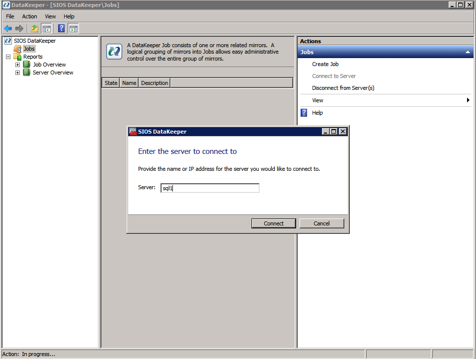
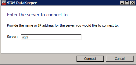
Once DataKeeper is installed you are ready to create your first DataKeeper job. Complete the following steps for each volume you want to replicate using the DataKeeper interface
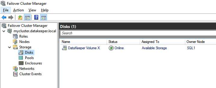
Use the DataKeeper interface to connect to both serversClick on create new job and give it a nameClick Yes to register the DataKeeper volume in the clusterOnce the volume is registered it will appear in Available Storage in Failover CLuster Manager
Create the iSCSI target server cluster
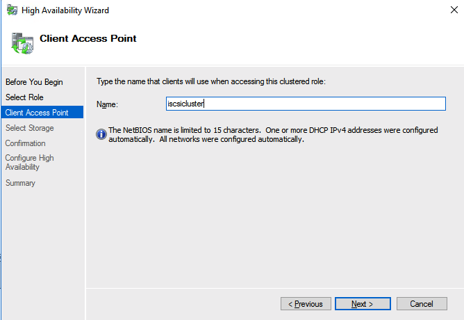
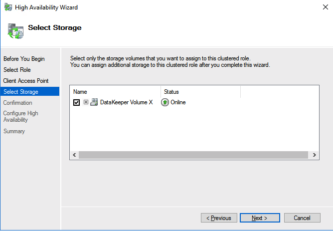
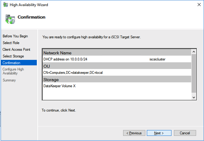
In this next step we will create the iSCSI target server role in our cluster. In an ideal world I would have a Powershell script that does all this for you, but for sake of time for now I’m just going to show you how to do it through the GUI. If you happen to write the Powershell code please feel free to share with the rest of us!
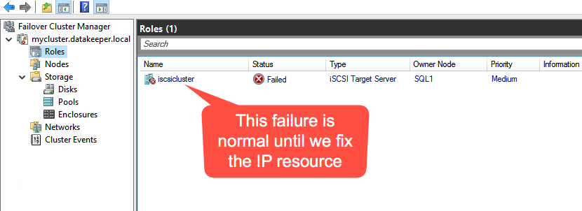
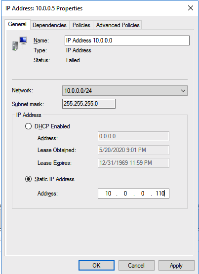
There is one problem with the GUI method. ou will wind up with a duplicate IP address in when the IP Resource is created, which will cause your cluster resource to fail until we fix it. I’ll walk through that process as well.
Go to the Properties of the failed IP Address resource and choose Static IP and select an IP address that is not in use on your network. Remember this address, we will use it in our next step when we update the load balancer.
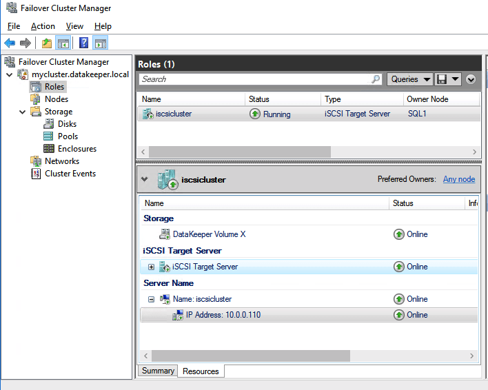
You should now be able to bring the iSCSI cluster resource online.
Update load balancer for iSCSI target server cluster resource
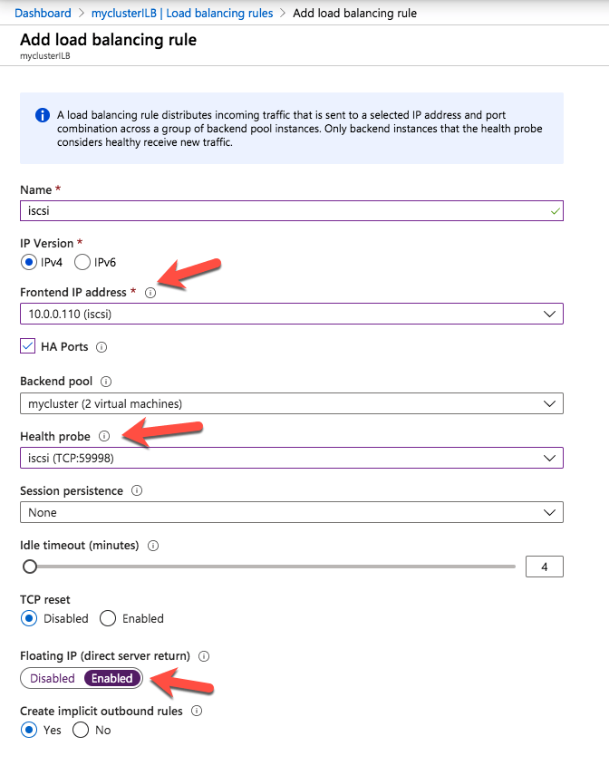
Like I mentioned earlier, clients can’t connect directly to the cluster IP address (10.0.0.110) we just created for the iSCSI target server cluster. We will have to update the load balancer we created earlier as shown below.
Start by adding a new frontend IP address that uses the same IP address that the iSCSI Target cluster IP resource uses. Add a second health probe on a different port. Remember this port number, we will use it again in the powershell script we run next We add one more load balancing rule. Make sure to change the Frontend IP address and Health probe to use the ones we just created. Also make sure direct server return is enabled.
The final step to allow the load balancer to work is to run the following Powershell script on one of the cluster nodes. Make sure you use the new Healthprobe port, IP address and IP Resource name.
 PS C:\Users\dave.DATAKEEPER> $ClusterNetworkName = “Cluster Network 1”
$IPResourceName = “IP Address 10.0.0.0”
$ILBIP = “10.0.0.110”
Import-Module FailoverClusters
Get-ClusterResource $IPResourceName | Set-ClusterParameter -Multiple @{Address=$ILBIP;ProbePort=59998;SubnetMask="255.255.255.255";Network=$ClusterNetworkName;EnableDhcp=0}
WARNING: The properties were stored, but not all changes will take effect until IP Address 10.0.0.0 is taken offline and then online again.
Make sure to take the resource offline and online for the settings to take effect.
Create your clustered iSCSI targets
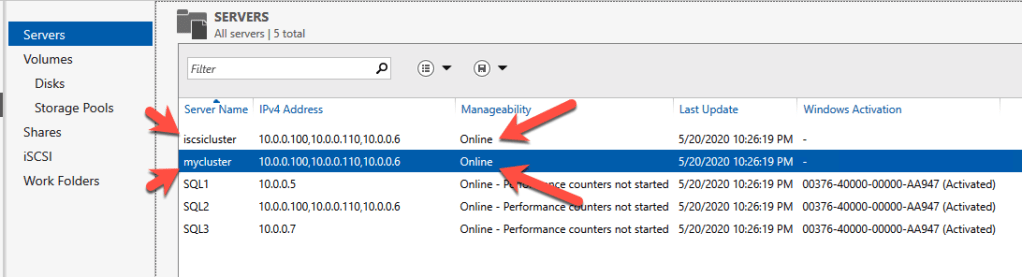
Before you begin, it is best to check to make sure Server Manager from BOTH servers can see the two cluster nodes, plus the two cluster name resources, and they both appear “Online” under manageability as shown below.
If either server has an issue querying either of those cluster names then the next steps will fail. If there is a problem I would double check all the steps you took to create the load balancer and the Powershell scripts you ran.
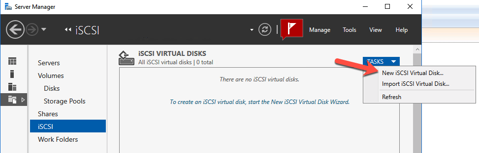
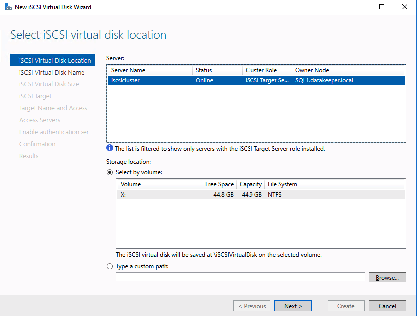
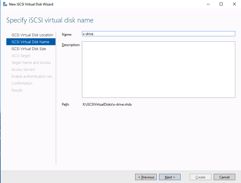
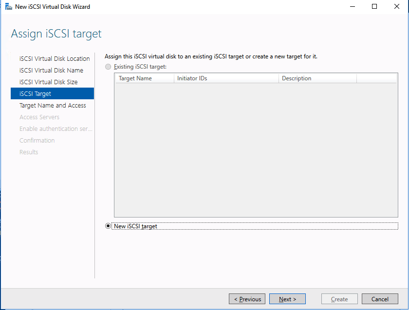
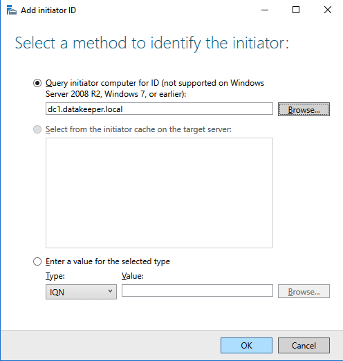
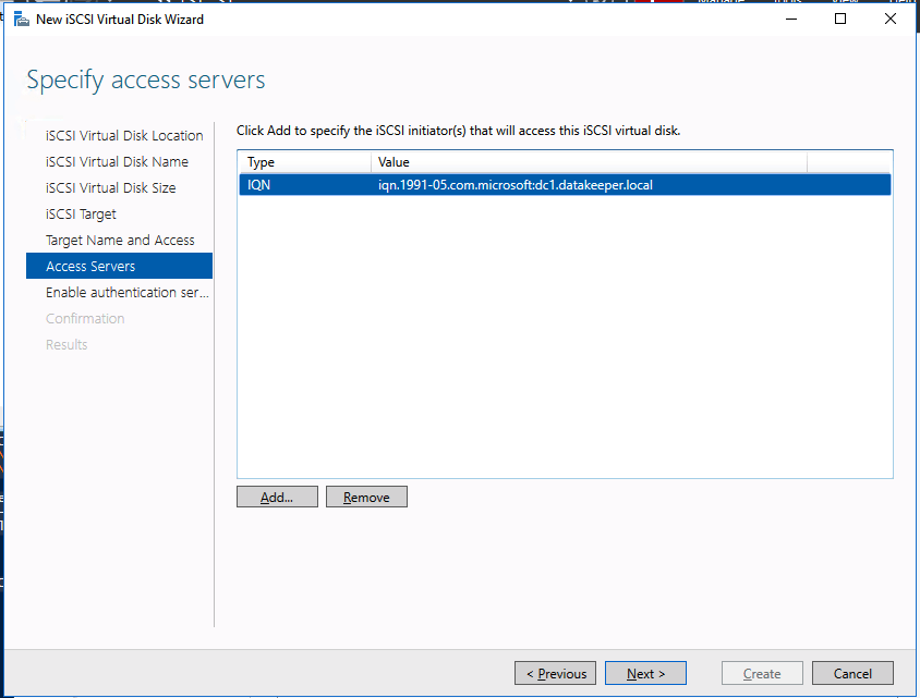
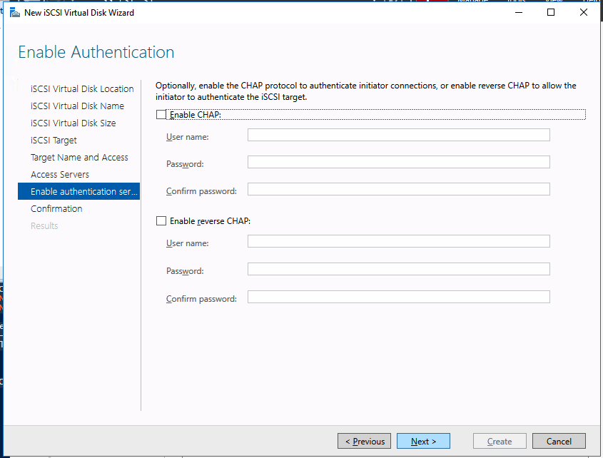
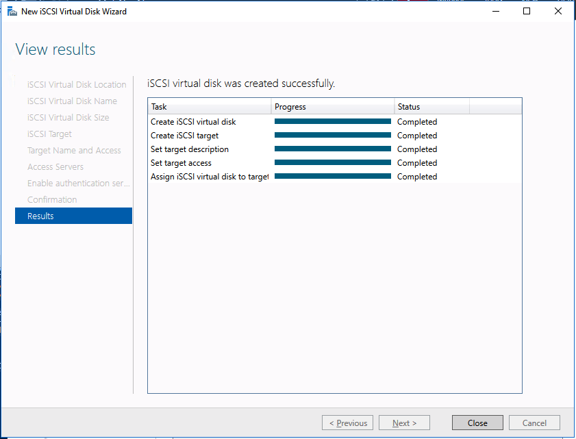
We are now ready to create our first clustered iSCSI targets. From either of the cluster nodes, follows the steps illustrated below as an example on how to create iSCSI targets.
Of course assign this to whichever server or servers will be connecting to this iSSI target.
And there you have it, you now have a functioning iSCSI target server in Azure.
If you build this leave a comment and me know how you plan to use it!
Once downloaded, navigate to the download location and run the executable with /x. This will give you an option to specify a location to extract the files to.
ENU\x64\SQLEXPRADV_x64_ENU.exe /x
Once the extraction completes, navigate to the extracted location and the following location:
SQL\1033_enu_lp\x64\setup\x64
Within that folder you should find SQLWriter.msi. Run this on the system where you want to update the SQL writer.
You now will be able to use ASR to do application consistent recovery points of SQL Server 2008 R2.
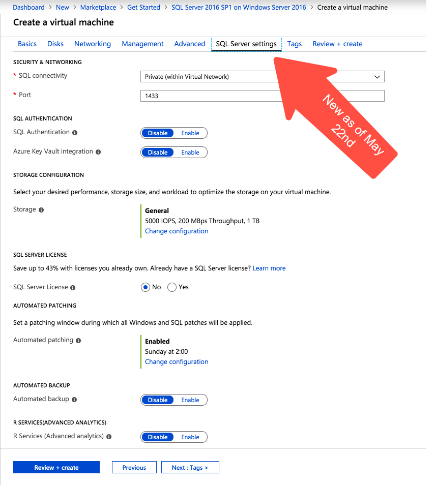
I just noticed today that there is a new blade in the Azure portal when creating a new SQL Server virtual machine. I’ve been looking for an announcement regarding this new Azure portal experience, but I haven’t found one yet. This feature wasn’t available when I took the screen shots for my last post on creating a SQL Server 2008 R2 FCI in Azure on April 19th, so it must be relatively new.
New Azure “SQL Server Settings” blade on the Azure portal
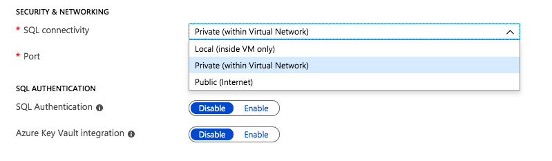
Most of the settings are pretty self explanatory. Under Security and Networking you can specify the port you want SQL to listen on. It also appears as if the Azure Security Group will be updated to allow different levels of access to the SQL instance: Local, Private or Public. Authentication options are also exposed in this new SQL Server settings blade.
Security, Networking and Authentication options are part of your SQL Server deployment
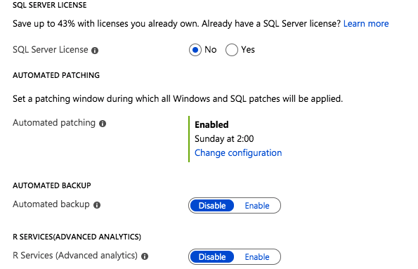
The rest of the features include licensing, patching and backup options. In addition, if you are deploying the Enterprise Edition of SQL Server 2016 or later you also have the option to enable SQL Server R Services for advanced analytics.
Licensing, Patching, Backup and R Services options can be automatically configured
All of those options are welcome additions to the Azure portal experience when provisioning a new SQL Server instance. I’m sure the seasoned DBA probably has a list of a few dozen other options they would like to tweak before a SQL Server deployment, but this is certainly a step in the right direction.
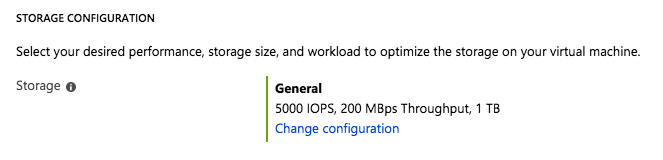
Storage Configuration Options
The most interesting new feature I have found on this blade is the Storage Configuration option.
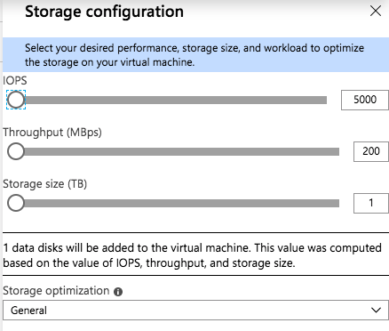
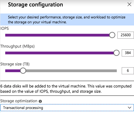
When you click on Change Configuration, you get the following blade.
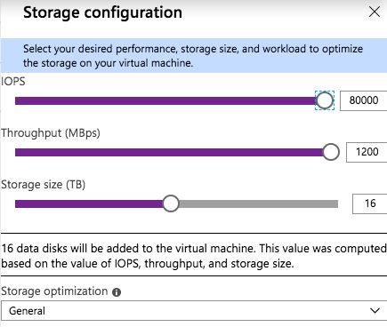
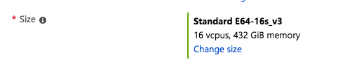
As you slide the IOPS slider to the right you will see the number of data disks increase, the Storage Size increase, and the Throughput increase. You will be limited to the max number of IOPS and disks supported by that instance size. You see in the screenshot below I am able to go as high as 80,000 IOPS when provisioning storage for a Standard E64-16s_v3 instance.
The Standard E64-16s_v3 instance size supports up to 80,000 IOPS
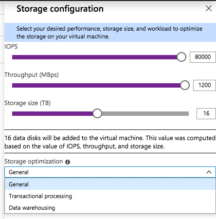
There is also a “Storage optimization” option. I haven’t tried all the different combinations to know exactly what the Storage optimization setting does. If you know how the different options change the storage configuration, leave me a comment, or we will just wait for the official documentation to be released.
For my test, I provisioned a Standard DS13 v2 instance and maxed out the IOPS at 25600, the max IOPS for that instance size. I also optimized the storage for Transactional processing.
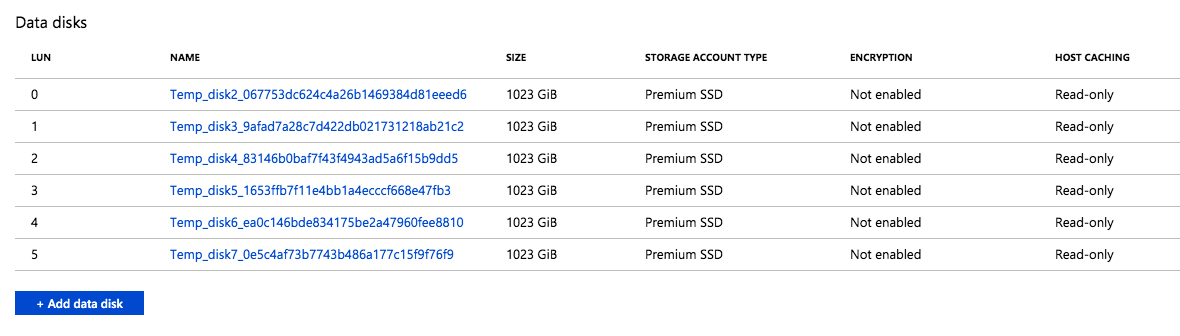
I found that when this instance was provisioned, six P30 premium disk were attached to the instance. This makes sense, since each P30 delivers 5000 IOPS, so it would take at least six of them to deliver the 25,600 IOPS requested. This also increased the Storage Size to 6 TB, since each P30 gives you one 1 TB of storage space. The Read-only host caching was also enabled on these disks.
The six disks were automatically provisioned and attached to the instance
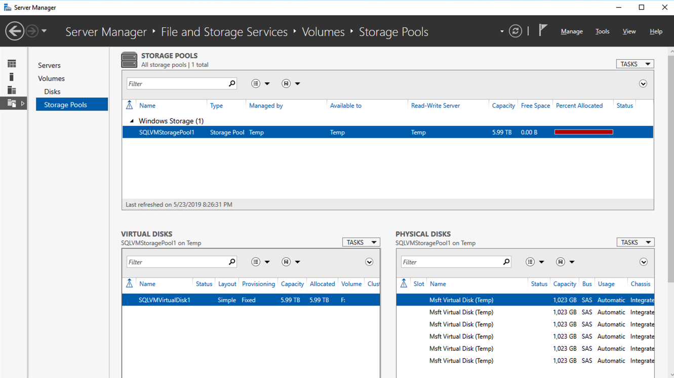
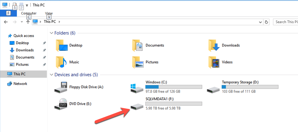
When I logged in to the instance to see what Azure had done with those disk I found that they had done exactly what I would have done; they created a single Storage Pool with the six P30 disks and created a Simple (aka, RAID 0) Storage Space and provisioned a single 6 TB F:\ drive.
This storage configuration wizard validates some of the cloud storage assumptions I made in my previous blog post, Storage Considerations for Running SQL Server in Azure. It seems like a single, large disk should suffice in most circumstances.
A Simple Storage Space consisting of the six P30s are presented as a single F:\ drive
I have found this storage optimization is not available in every Azure Marketplace offering. For example, if you are moving SQL Server 2008 R2 to Azure for the extended security updates you will find that this storage optimization in not available in the SQL2008R2/Windows Server 2008 R2 Azure Marketplace image. Of course, Storage Spaces was not introduced until Windows Server 2012, so that makes sense. I did verify that this option is available with the SQL Server 2012 SP4 on Windows Server 2012 R2 Azure Marketplace offering.
There is a minor inconvenience however. In addition to adding this new Storage configuration option on SQL Server settings blade, they also removed the option to add Data Disks on the Disks blade. So if I wanted to provision additional storage without creating a Storage Space, I would have to create the instance first and then come back and add Data disks after it the virtual machine is provisioned.
Final thoughts
All of the SQL Server configuration options in this new Azure blade are welcome additions. I would love to see the list tunable settings grow. Information text should include guidance on current best practices for each tunable.
What SQL Server or Windows OS tunables would you like to see exposed as part of the provisioning process to make your life as a DBA easier? Not only would these tunables make your life easier, but they would also make the junior DBA look like a season pro by guiding them through all the current SQL Server configuration best practices.
I think the new Storage configuration option is probably the most compelling new addition. Prior to the Storage configuration wizard, users had to be aware of the limits of their instance size, the limits of the storage they were adding, and have the wherewithal to stripe together multiple disks in a Simple Storage Space to get the maximum IOPS. A few years ago I put together a simple Azure Storage Calculator to help people make these decisions. My calculator is currently outdated, but this new Storage configuration option may make it obsolete anyway.
I would love to see this Storage configuration wizard included as a standard offering in the Disks blade of every Windows instance type, rather than just the SQL Server instances. I would let the user choose to use the new Storage configuration “Wizard” experience, or the “Classic” experience where you manually add and manage storage.
If you are like me and were unable to get away from the office to attend Microsoft Build 2019 you will be glad to know that Microsoft has published all the sessions and are available online at no charge.
I’m more of an infrastructure guy, so some of the more interesting announcements to me were the following.
Azure VMware Solutions is now generally available – I guess if I was heavily invested in VMware and was looking to expand into Azure this announcement would certainly open up some interesting possibilities. It looks like if I use a bare-metal instance or dedicated instance I can basically have an ESX host running in Azure. I guess if you are doing a hybrid-cloud deployment and want to easily move workloads back and forth between on-prem and Azure his makes sense. If this excites you leave me a comment telling me why.
Azure Quickstart Center enables new customers to build cloud projects with confidence – I haven’t looked into this yet, but this looks VERY interesting to me if it is what I think it is. As cloud adoption continues to grow so does the required skill set of the IT professional. Infrastructure as Code (IaC) is one of those skills the wise IT professional will want to become comfortable with.
Just two years ago I would talk to customers and this skill set was non-existent, or really just something the largest IT consultants or cloud providers had any experience in. Over the past year I have seen this skill set become more common with the customers I work with and is often the preferred deployment method. The IaS technology has also matured over that period.
I predict that if you don’t already manage your cloud deployment with IaC you will be in the near future. I’m hopeful that this new offering from Microsoft could be a great intro to those IT professionals looking to gain some IaC experience and knowledge. After I have had a look at it I’ll post a follow-up article.
If you are deploying SQL Server in Azure, or any Cloud platform for that matter, instead of just provisioning storage like you did for your on-premises deployments for many years, you may consider that storage in the Azure isn’t exactly like the storage you may have had access to on-premises. Some traditional “best practices” may wind up costing you additional money and give you less than optimal performance, all while not providing you any of the intended benefits. Much of what I am about to discuss is also described in Performance Guidelines for Azure in SQL Server Virtual Machines.
Disk Types
I’m not here to tell you that you must use UltraSSD, Premium Storage, or any other disk type. You just need to be aware that you have options, and what each disk type brings to the table. Of course, like anything else in the cloud, the more money you spend, the more power, speed, throughput, etc., you will achieve. The trick is finding the optimal configuration so that you spend just enough to achieve the desired results.
Size DOES Matters
Like many things in the cloud, certain specs are tied together. For servers if you want more RAM you often get more CPU, even if you didn’t NEED more CPU. For storage, IOPS, throughput and size are all tied together. If you want more IOPS, you need a bigger disk. If you need more space, you also get more IOPS. Of course you can jump between storage classes to circumvent that to some extent, but it still holds true that if you need more IOPS, you also get more space on any of the different storage types.
The size of your virtual machine instance also matters. Regardless of what storage configuration you eventually go with, the overall throughput will be capped at whatever the instance size allows. So once again, you may need to pay for more RAM and CPU than you need, just to achieve your desired storage performance. Make sure you understand what your instance size can support in terms of max IOPS and MBps throughput. Many times the instance size will turn out to be the bottleneck in a perceived storage performance problem in Azure.
Use RAID 0
RAID 0 is traditionally the 3rd rail of storage configuration options. Although it provides the best combination of performance and storage utilization of any RAID option, it does so at the risk of a catastrophic failure. If just a single disk in a RAID 0 stripe set should fail, the entire stripe set fails. So traditionally RAID 0 is only used in scenarios where data loss is acceptable and high performance is desirable.
However, in Azure software RAID 0 is desirable and even recommended in many situations. How can we get away with RAID 0 in Azure? The answer is easy. Each disk you present to an Azure virtual machine instance already has triple redundancy on the backend, meaning you would need to have multiple failures before you would lose your stripe set. By using RAID 0, you can combine multiple disks and the overall performance of the combined stripe set will increase by 100% for each additional disk you add to the stripe set.
So for example, if you had a requirement of 10,000 IOPS, you might think that you need UltraSSD since Premium Storage maxes out at 7,500 IOPS with a P50. However, if you put two P50s in a RAID 0, you now have the potential to achieve up to 15,000 IOPS, assuming you are running a Standard_F16s_v2 or similarly large instance size that supports that many IOPS.
In Windows 2012 and later, RAID 0 is achieved by creating a Simple Storage Space. In Windows Server 2008 R2 you can use Dynamic Disks to create a RAID 0 Striped Volume. Just a word of caution, if you are going to use a local Storage Space and also configure Availability Groups or a SANless Failover Cluster Instance with DataKeeper, it is best to configure your storage BEFORE you create a cluster.
Just a reminder, you only have about two more months to move your SQL Server 2008 R2 instances to Azure. Check out my post on how to deploy a SQL Server 2008 R2 FCI on Azure to ensure high availability.
Don’t bother separating log and data files
Traditionally log and data files would reside on different physical disks. Log files tend to have a lot of write activity and data files tend to have more read activity, so sometimes storage would be optimized based on those characteristics. It was also desirable to keep log and data files on different disks for recovery purposes. If you should lose one or the other, with a proper backup strategy in place you could recover your database with no data loss.
With cloud based storage, the likelihood of losing just a single volume is EXTREMELY low. If by chance you lose storage, it is likely your entire storage cluster, along with the triple redundancy, went to lunch. So while it may feel right to put logs in E:\ logs and data in F:\data, you really are doing yourself a disservice. For example, if you provision a P20 for logs and a P20 for data, each volume will be 512 GiB in size and capped at 2,300 IOPS. And just think, you may not need all that size for log files, but it might not give you much room to grow for your data files, which will eventually require moving to a more expensive P30 just for the extra space.
Wouldn’t it be much nicer to simply stripe those two volumes together into a nice large 1 TB volume that supports 4,600 IOPS? By doing that both the log and data files can take advantage of the increased IOPS and you have also just optimized your storage utilization and decreased your cloud storage cost by putting off the move to a P30 disk for your data file.
The same holds true files and filegroups. Really think hard about what you are doing and whether it still makes sense once you move to the cloud. What makes sense might be counter intuitive to what you have done in the past. When in doubt, follow the KISS rule, Keep It Simple Stupid! The beauty of the cloud is you can always add more storage, increase instance size, or do whatever it takes to optimize performance vs. cost.
What to do about TempDB
Use the local SSD, aka, the D: drive. The D drive is going to be the best location for your tempdb. Because it is a local drive the data is considered “temporary”, meaning it can be lost if a server is moved, rebooted, etc. That’s okay, tempdb is recreated each time SQL starts anyway. The local SSD is going to be fast and have low latency, but because it is local the reads and writes to it do not contribute to the overall storage IOPS limit of the instance size, so effectively it is FREE IOPS, so why not take advantage? If you are building a SANless SQL Server FCI with SIOS DataKeeper, be sure to create a non-mirrored volume resource of the D drive so you don’t needlessly replicate TempDB.
Mount Points Become Obsolete
Mount Points are commonly used in SQL Server FCI configurations when multiple instances of SQL Server are installed on the same Windows Cluster. This reduces the overall cost of SQL Server licenses and can help save cost by driving higher server utilization. As we discussed in the past, typically there might be five or more drives associated with each SQL Server instance. If each of those drives had to consume a drive letter you would run out of letters in just about three to four instances. So instead of giving each drive a letter, mount points were used so that each instance could just be serviced by a single drive letter, the root drive. The root drive has mount points that map to separate physical disks that don’t have drive letters.
However, as we discussed above, the concept of using a bunch of individual disks really doesn’t make a lot of sense in the cloud, hence mount points become obsolete in the cloud. Instead, create a RAID 0 stripe we as described and each clustered instance SQL Server will simply have its own individual volume that is optimised for space, performance and cost. This solves the problem of running out of drive letters and gives you much better storage utilization and performance while also reducing the cost of your cloud storage.
Conclusions
This post is meant as a jumping off point, not a definitive guide. The main point of the post is to get you thinking differently about cloud and storage as it pertains to running SQL Server. Don’t simply take what you did on-premise and recreate it in the cloud, that will almost always result in less than optimal performance and a much larger storage bill than necessary.
On July 9, 2019, support for SQL Server 2008 and 2008 R2 will end. That means the end of regular security updates. However, if you move those SQL Server instances to Azure or Azure Stack (I will simply refer to both as Azure for the rest of the guide), Microsoft will give you three years of Extended Security Updates at no additional charge. If you are currently running SQL Server 2008/2008 R2 and you are unable to update to a later version of SQL Server before the July 9th deadline, you will want to take advantage of this offer rather than running the risk of facing a future security vulnerability. An unpatched instance of SQL Server could lead to data loss, downtime or a devastating data breach.
One of the challenges you will face when running SQL Server 2008/2008 R2 in Azure is ensuring high availability. On premises you may be running a SQL Server Failover Cluster (FCI) instance for high availability, or possibly you are running SQL Server in a virtual machine and are relying on VMware HA or a Hyper-V cluster for availability. When moving to Azure, none of those options are available. Downtime in Azure is a very real possibility that you must take steps to mitigate.
In order to mitigate the possibility of downtime and qualify for Azure’s 99.95% or 99.99% SLA, you have to leverage SIOS DataKeeper. DataKeeper overcomes Azure’s lack of shared storage and allows you to build a SQL Server FCI in Azure that leverages the locally attached storage on each instance. SIOS DataKeeper not only supports SQL Server 2008 R2 and Windows Server 2008 R2 as documented in this guide, it supports any version of Windows Server, from 2008 R2 through Windows Server 2019 and any version of SQL Server from from SQL Server 2008 through SQL Server 2019.
This guide will walk through the process of creating a two-node SQL Server 2008 R2 Failover Cluster Instance (FCI) in Azure, running on Windows Server 2008 R2. Although SIOS DataKeeper also supports clusters that span Availability Zones or Regions, this guide assumes each node resides in the same Azure Region, but different Fault Domains. SIOS DataKeeper will be used in place of the shared storage normally required to create a SQL Server 2008 R2 FCI.
Pre-Requisites
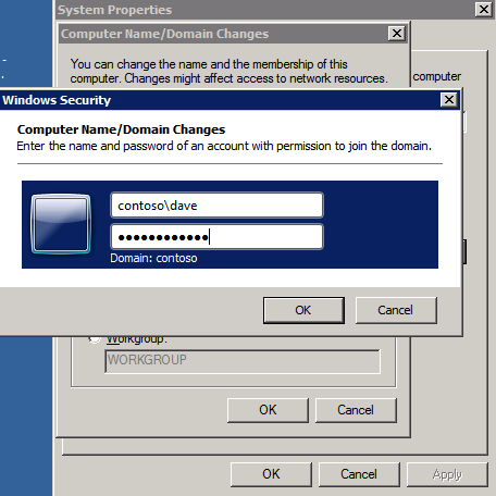
Active Directory This guide assumes you have an existing Active Directory Domain. You can manage your own Domain Controllers or use Azure Active Directory Domain Services. For this tutorial we will connect to a domain called contoso.local. Of course you will connect to your own domain when following this tutorial.
Open Firewall Ports – SQL Server:1433 for Default Instance – Load Balancer Health Probe: 59999 – DataKeeper: these firewall rules are added to the Windows host based firewall automatically during installation. For details on which ports are opened consult the SIOS documentation. – Keep in mind, if you have any network based security in place that blocks ports between the cluster nodes you will need to account for these ports there as well.
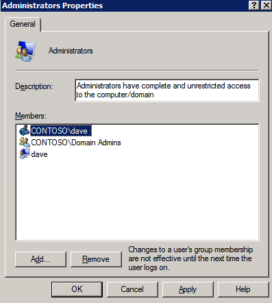
DataKeeper Service Account Create a Domain account. We will specify this account when we install DataKeeper. This account will need to be added to the Local Administrators group on each node of the cluster.
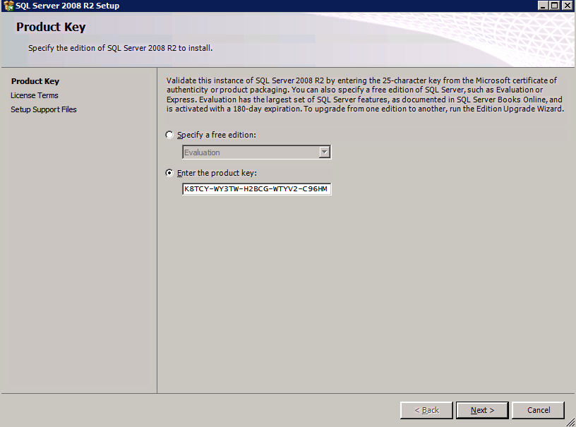
Create the first SQL Server Instance in Azure
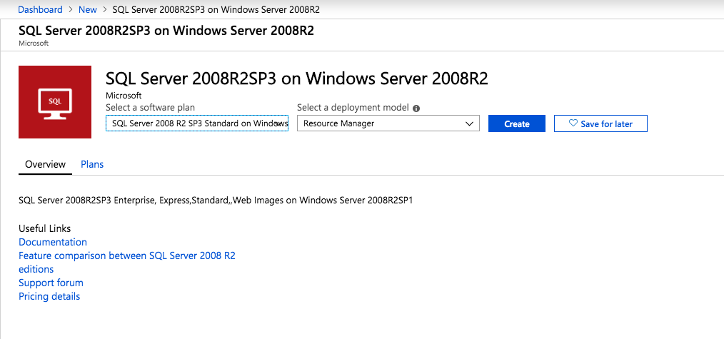
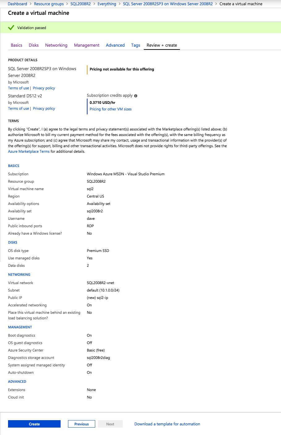
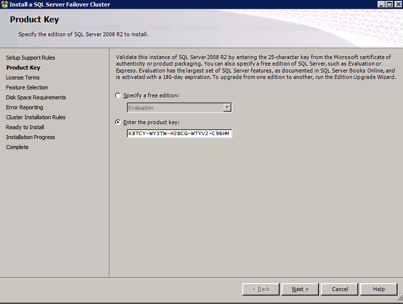
This guide will leverage the SQL Server 2008R2SP3 on Windows Server 2008R2 image that is published in the Azure Marketplace.
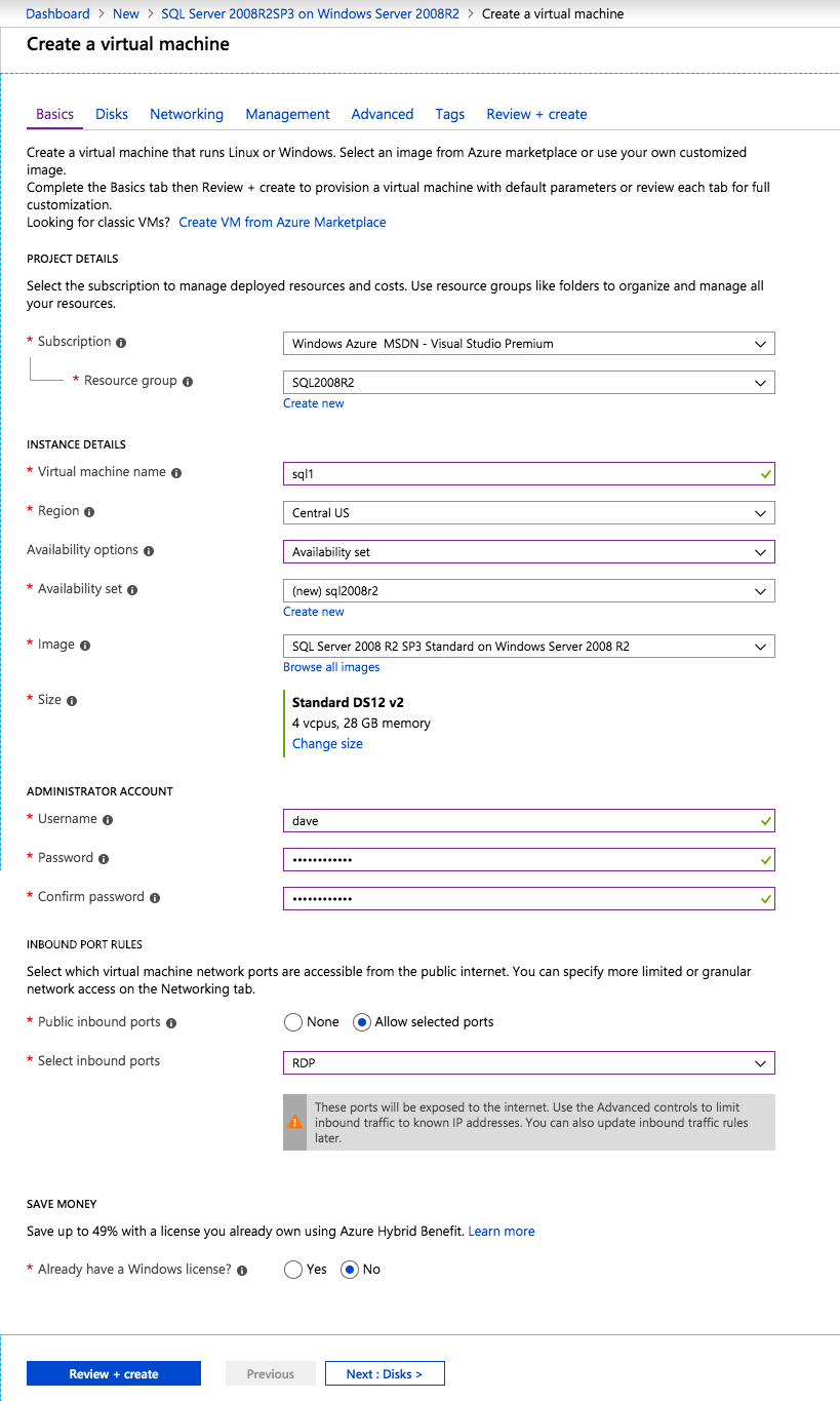
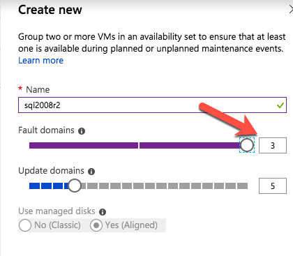
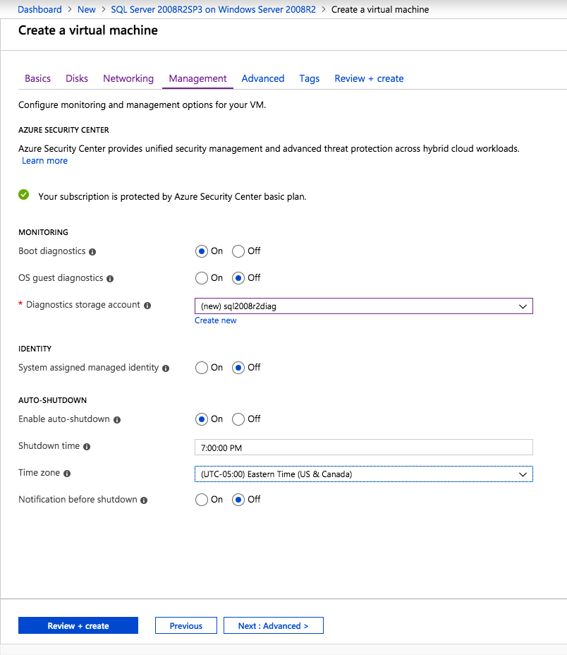
When you provision the first instance you will have to create a new Availability Set. During this process be sure to increase the number of Fault Domains to 3. This allows the two cluster nodes and the file share witness each to reside in their own Fault Domain.
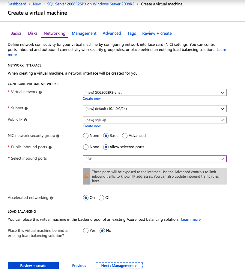
If you don’t already have a virtual network configured, allow the creation wizard to create a new one for you.
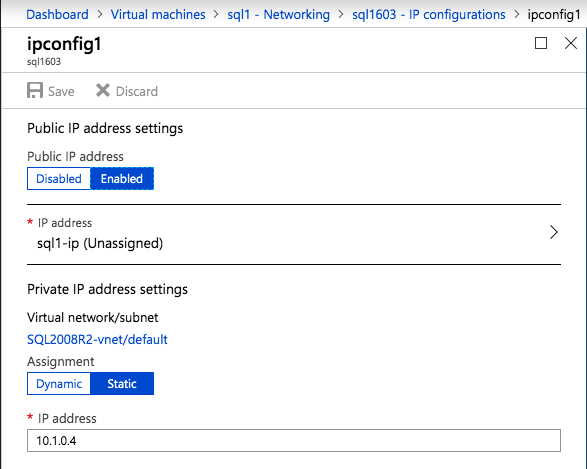
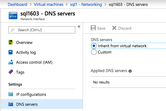
Once the instance is created, go in to the IP configurations and make the Private IP address static. This is required for SIOS DataKeeper and is best practice for clustered instances.
Make sure that your virtual network is configured to set the DNS server to be a local Windows AD controller to ensure you will be able to join the domain in a later step.
After the virtual machines are provisioned, add at least two additional disks to each instance. Premium or Ultra SSD are recommended. Disable caching on the disks used for the SQL log files. Enable read-only caching on the disk used for the SQL data files. Refer to Performance guidelines for SQL Server in Azure Virtual Machines for additional information on storage best practices.
Create the 2nd SQL Server Instance in Azure
Follow the same steps as above, except be sure to place this instance in the same virtual network and Availability Set that you created with the 1st instance.
Create a File Share Witness (FSW) Instance
In order for the Windows Server Failover Cluster (WSFC) to work optimally you are required to create another Windows Server instance and place it in the same Availability Set as the SQL Server instances. By placing it in the same Availability Set you ensure that each cluster node and the FSW reside in different Fault Domains, ensuring your cluster stays on line should an entire Fault Domain go off line. This instances does not require SQL Server, it can be a simple Windows Server as all it needs to do is host a simple file share.
This instance will host the file share witness required by WSFC. This instance does not need to be the same size, nor does it require any additional disks to be attached. It’s only purpose is to host a simple file share. It can in fact be used for other purposes. In my lab environment my FSW is also my domain controller.
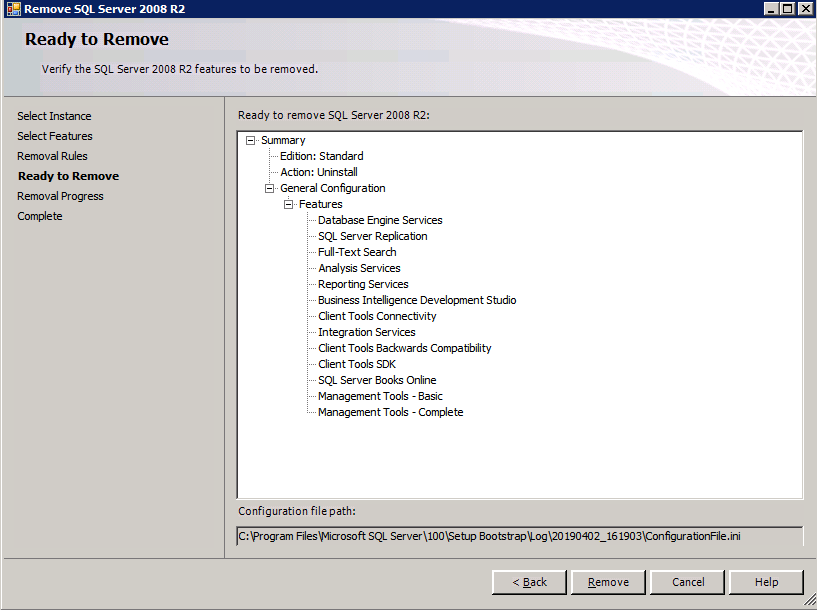
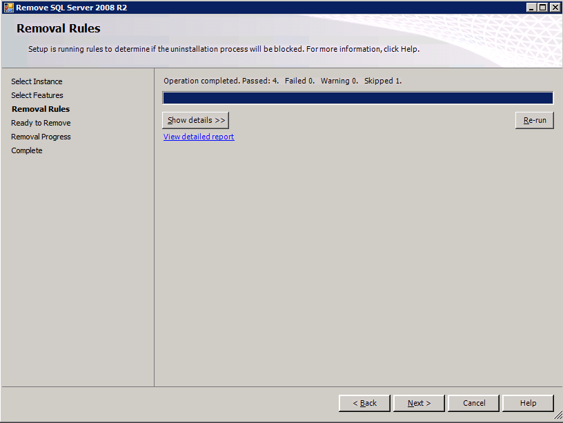
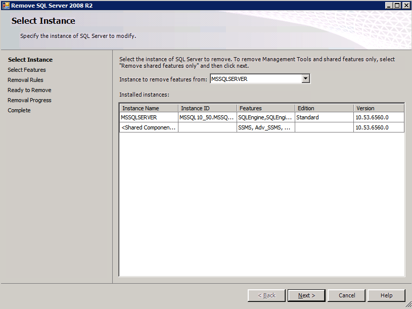
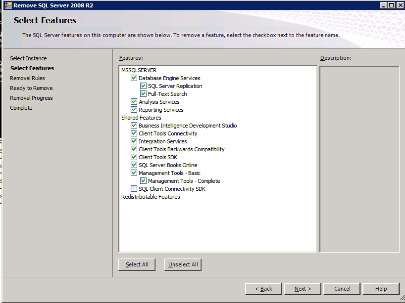
Uninstall SQL Server 2008 R2
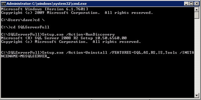
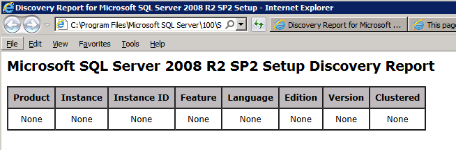
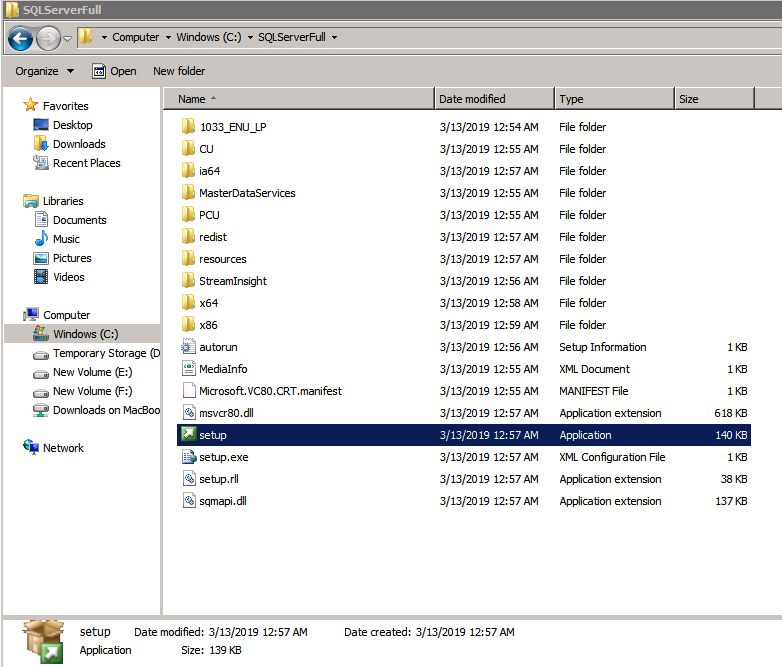
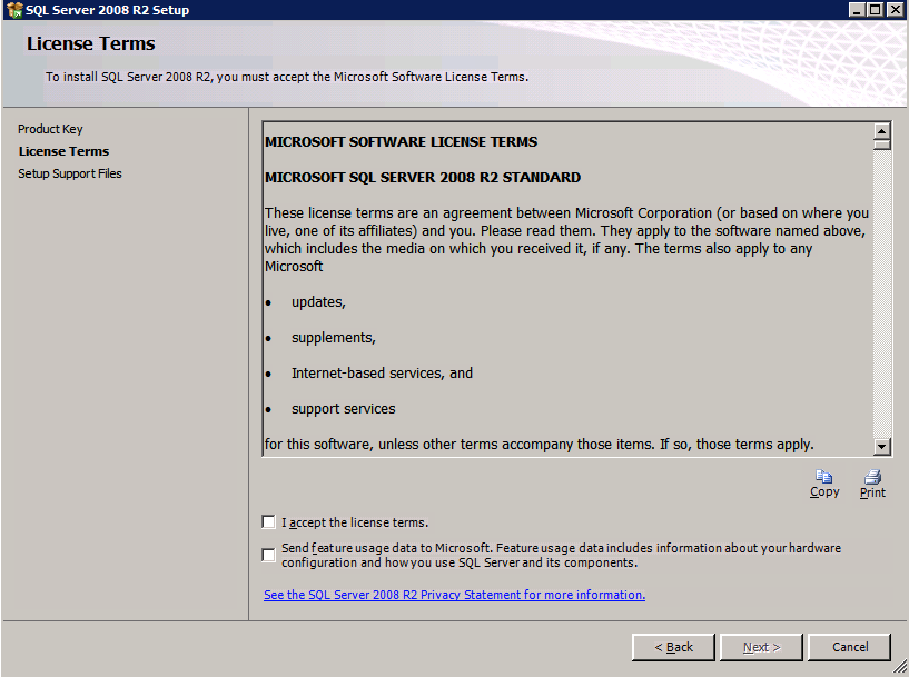
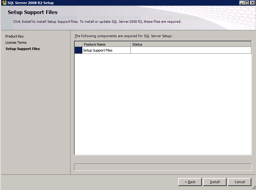
Each of the two SQL Server instances provisioned already have SQL Server 2008 R2 installed on them. However, they are installed as standalone SQL Server instances, not clustered instances. SQL Server must be uninstalled from each of these instances before we can install the cluster instance. The easiest way to do that is to run the SQL Setup as shown below.
When you run setup.exe /Action-RunDiscovery you will see everything that is preinstalled
setup.exe /Action=RunDiscovery
Running setup.exe /Action=Uninstall /FEATURES=SQL,AS,RS,IS,Tools /INSTANCENAME=MSSQLSERVER kicks off the uninstall process
Running setup.exe /Action-RunDiscovery confirms the uninstallation completed
setup.exe /Action-RunDiscovery
Run this uninstallation process again on the 2nd instance.
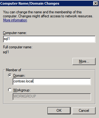
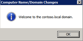
Add instances to the Domain
All three of these instances will need to be added to a Windows Domain. As mentioned in the Prerequisites section, you must have access to join an existing Windows Active Directory. In our case, we are joining a domain called contoso.local.
Add Windows Failover Clustering Feature
The Failover Clustering Feature needs to be added to the two SQL Server instances
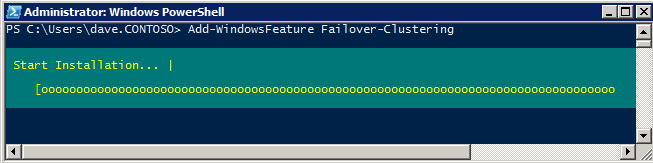
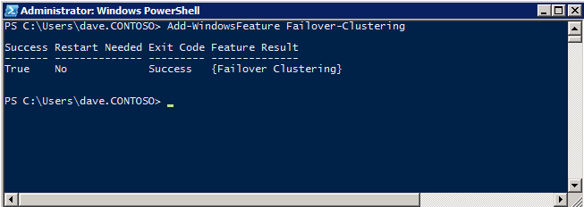
Add-WindowsFeature Failover-Clustering
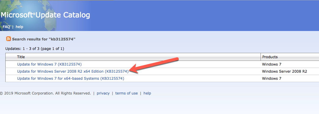
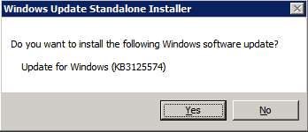
Install Convenience Rollup Update for Windows Server 2008 R2 SP1
There is a critical update ( kb2854082) that is required in order to configure a Windows Server 2008 R2 instance in Azure. That update and many more are included in the Convenience Rollup Update for Windows Server 2008 R2 SP1. Install this update on each of the two SQL Server instances.
Format the Storage
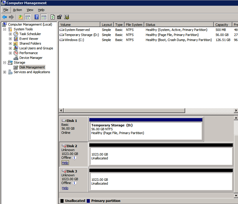
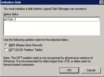
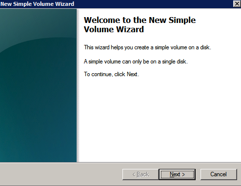
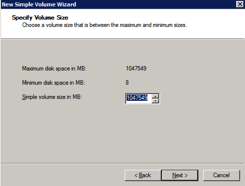
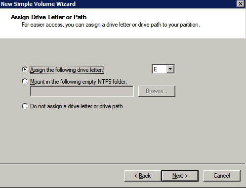
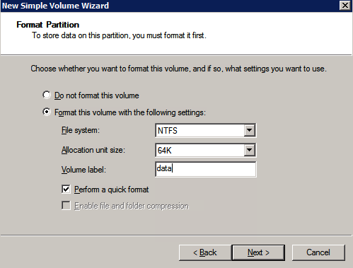
The additional disks that were attached when the two SQL Server instances were provisioned need to be formatted. Do the following for each volume on each instance.
“NTFS allocation unit size: When formatting the data disk, it is recommended that you use a 64-KB allocation unit size for data and log files as well as TempDB.”
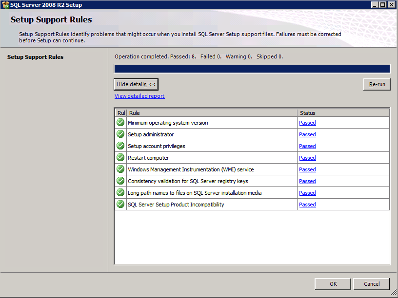
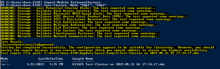
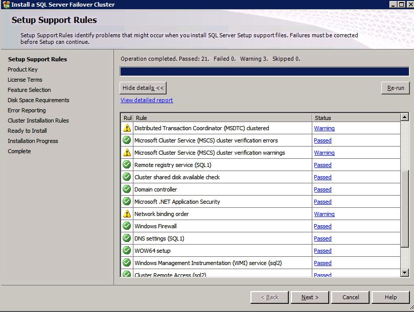
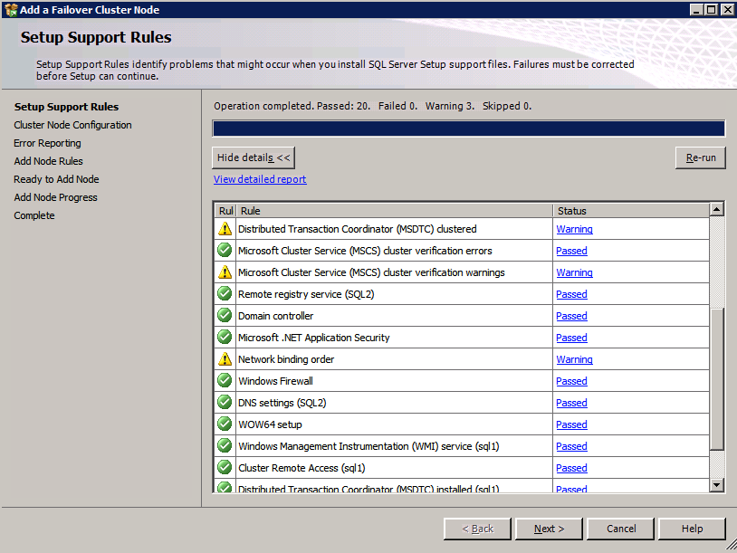
Run Cluster Validation
Run cluster validation to ensure everything is ready to be clustered.
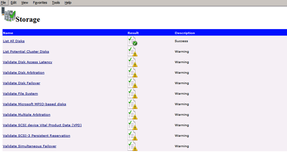
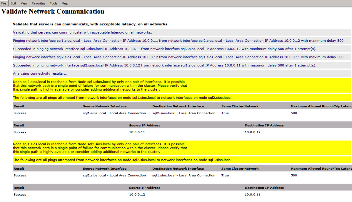
Your report will contain WARNINGS about Storage and Networking. You can ignore those warnings as we know there are no shared disks and only a single network connection exists between the servers. You may also receive a warning about network binding order which can also be ignored. If you encounter any ERRORS you must address those before you continue.
Since there are no “Potential Cluster DIsks” available, the first test throws a warning and all the subsequent disks test are skipped. This is expected since we will be using just local disks replicated with SIOS DataKeeper.The Validate Network Communication tests warn about just a single network being available between cluster nodes. You can ignore this warning since the network redundancy is handled at the virtual layer by Azure.
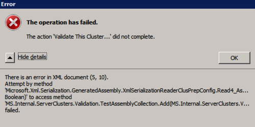
Error trying to run Cluster Validation?
I have encountered this error on a few occasions and I’m still trying to sort out under what conditions this occurs. Occasionally you will find that test-cluster fails to run as described in the forum post.
Test-Cluster
Unable to Validate a Cluster Configuration. The operation has failed. The action validate a configuration did not complete
There is an error in XML document (5, 73).

Attempt by method

Microsoft.Xml.Serialzation.GeneratedAssembly.XmlSerialzationReaderClusterPrep.Config.Read4_As...Bolean) to access method

MS.Internal.ServerClusters.Validation.TestAssemblyCollection.Add(MS.Internal.ServerClusters.V....Failed
If this happens to you, I have found the following fix recommended in the forum post works for me.
Inside C:\Windows\System32\WindowsPowerShell\v1.0 make a copy of powershell_ise.exe.config file (make a copy inside C:\Windows\System32\WindowsPowerShell\v1.0)- rename it to powershell.exe.config

Open it with notepad- delete current config line and paste:
<?xml version="1.0" encoding="utf-8" ?>
<configuration>
  <system.xml.serialization>
    <xmlSerializer useLegacySerializerGeneration="true"/>
  </system.xml.serialization>
</configuration>
- save and run test-cluster
While this fix will allow you to run test-cluster from Powershell, I have found that running Validate through the GUI still throws an error, even with this fix. I have a query in to Microsoft to see if they have a solution, but for now if you need to run cluster Validation you may have to use Test-Cluster in Powershell.
Create the Cluster
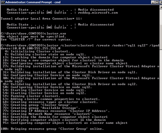
Best practices for creating a cluster in Azure would be to use Powershell to create a cluster, specifying a static IP address. Powershell allows us to specify a Static IP Address, whereas the GUI method does not. Unfortunately, Azure’s implementation of DHCP does not work well with WSFC, so if you use the GUI method you will wind up with a duplicate IP address as the Cluster IP Address that will need to be fixed before the cluster is usable.
However, what I have found is that the typical New-Cluster powershell command with the -StaticAddress command doesn’t work. To avoid the problem of the duplicate IP address, we have to resort to the cluster.exe utility and run the following command.
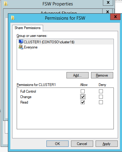
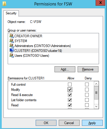
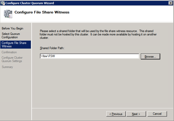
Next we need to add the File Share Witness. On the 3rd server we provisioned as the FSW, create a folder and share it as shown below. You will need to grant the Cluster Name Object (CNO) read/write permissions at both the Share and Security levels as shown below.
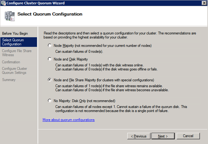
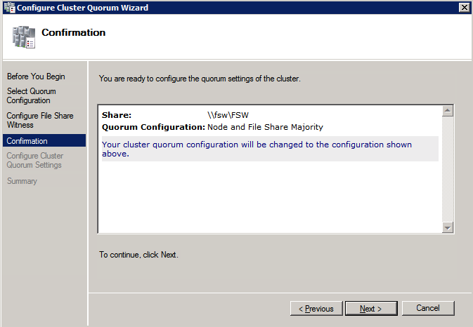
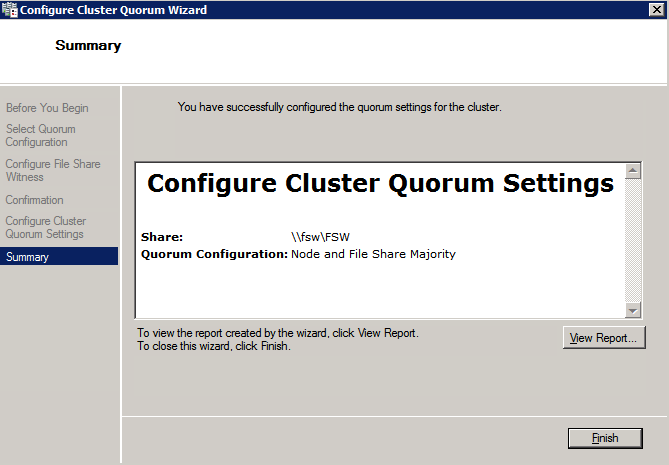
Once the share is created, run the Configure Cluster Quorum wizard on one of the cluster nodes and follow the steps illustrated below.
Install DataKeeper
Install DataKeeper on each of the two SQL Server cluster nodes as shown below.
This is where we will specify the Domain account we added to each of the local Domain Administrators group.
Configure DataKeeper
Once DataKeeper is installed on each of the two cluster nodes you are ready to configure DataKeeper.
NOTE – The most common error encountered in the following steps is security related, most often by pre-existing Azure Security groups blocking required ports. Please refer to the SIOS documentation to ensure the servers can communicate over the required ports.
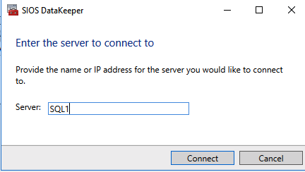
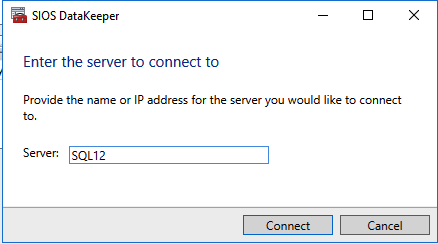
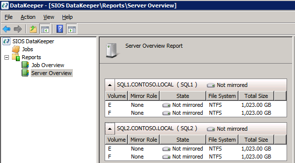
First you must connect to each of the two nodes.
If everything is configured properly, you should then see the following in the Server Overview report.
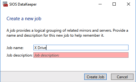
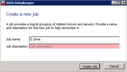
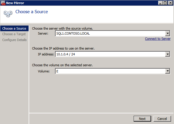
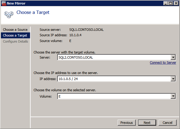
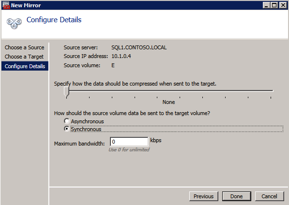
Next, create a New Job and follow the steps illustrated below
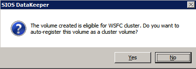
Choose Yes here to register the DataKeeper Volume resource in Available Storage
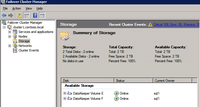
Complete the above steps for each of the volumes. Once you are finished, you should see the following in the WSFC UI.
You are now ready to install SQL Server into the cluster.
NOTE – At this point the replicated volume is only accessible on the node that is currently hosting Available Storage. That is expected, so don’t worry!
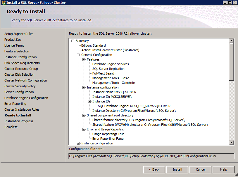
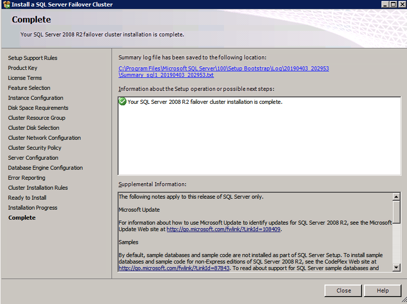
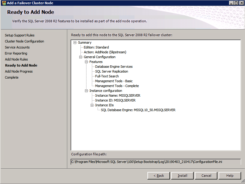
Install SQL Server on the first node
If you want to script the installation, I have included the example below of a scripted cluster installation of SQL Server 2008 R2 into the first node of cluster. The script to add a node to existing cluster is found further down in the guide.
If you prefer to use the GUI, just follow along with the screenshots below.
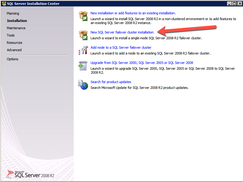
On the first node, run the SQL Server setup.
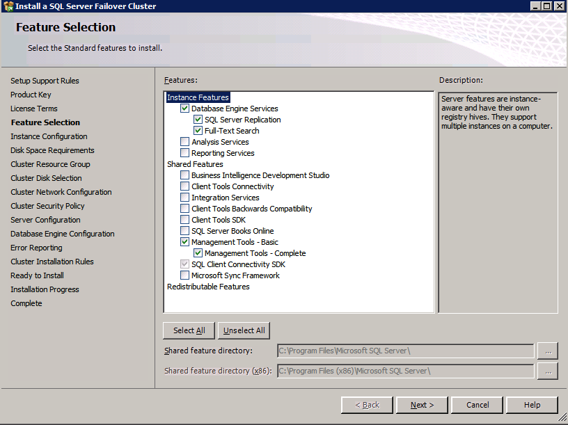
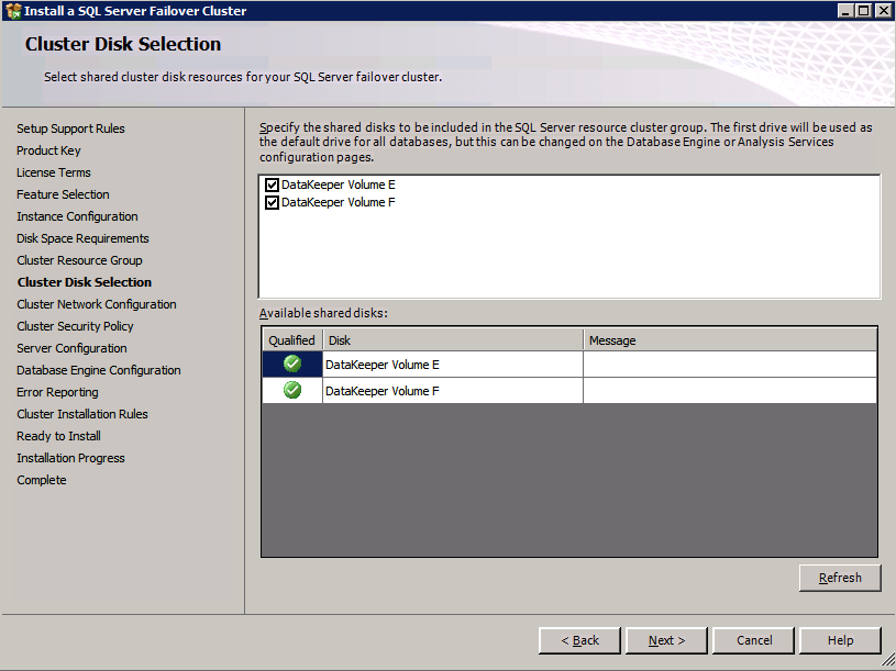
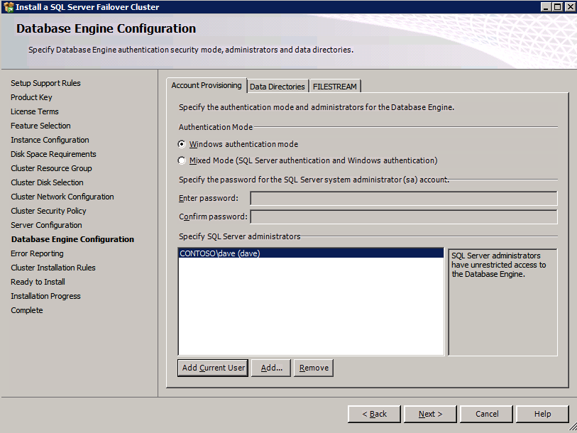
Choose New SQL Server Failover Cluster Installation and follow the steps as illustrated.
Choose only the options you need.
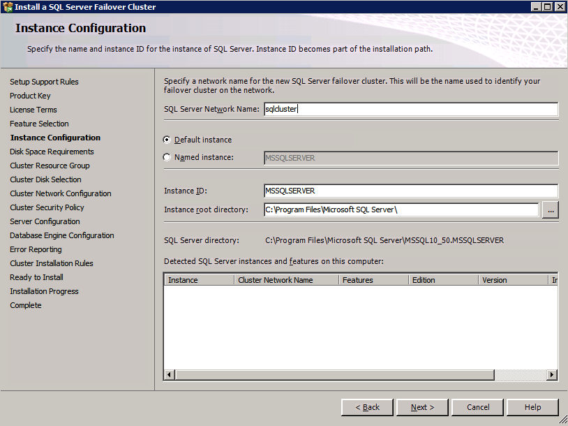
Please note, this document assumes you are using the Default instance of SQL Server. If you use a Named Instance you need to make sure you lock down the port that it listens on, and use that port later on when you configure the load balancer. You also will need to create a load balancer rule for the SQL Server Browser Service (UDP 1434) in order to connect to a Named Instance. Neither of those two requirements are covered in this guide, but if you require a Named Instance it will work if you do those two additional steps.
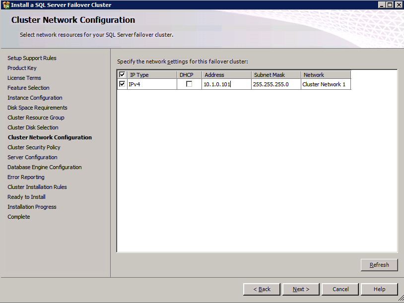
Here you will need to specify an unused IP address
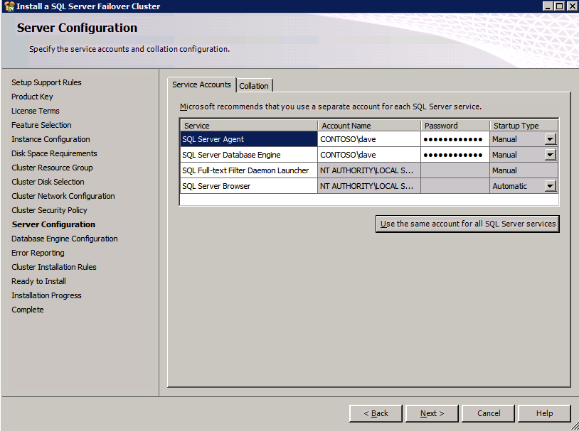
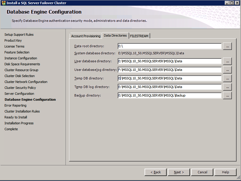
Go to the Data Directories tab and relocate data and log files. At the end of this guide we talk about relocating tempdb to a non-mirrored DataKeeper Volume for optimal performance. For now, just keep it on one of the clustered disks.
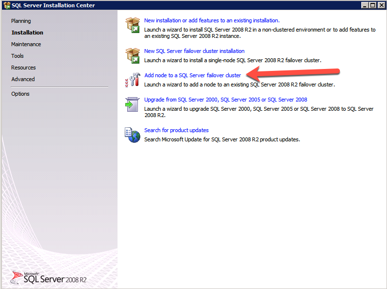
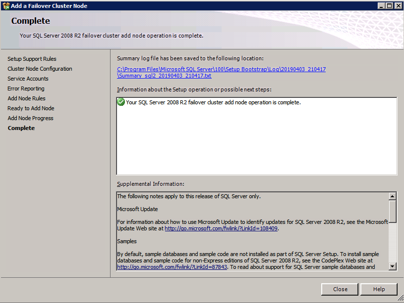
Install SQL Server on the second node
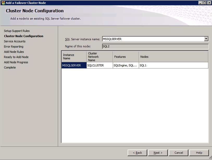
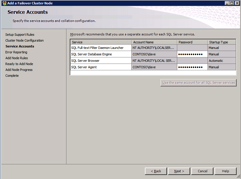
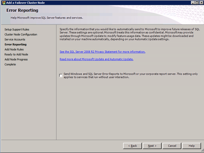
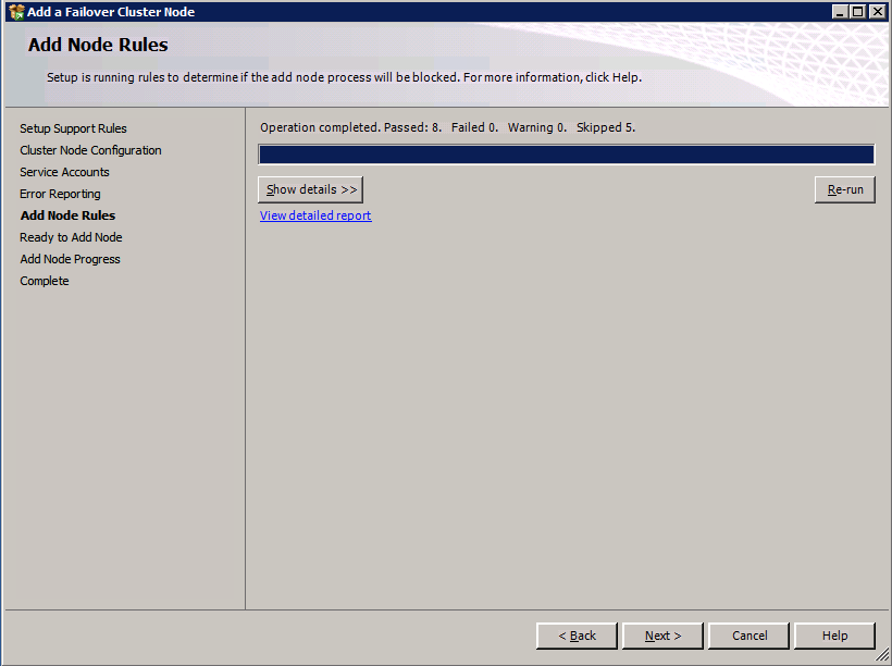
Below is an example of the command you can run to add an additional SQL Server 2008 R2 node into an existing cluster.
If you prefer using the GUI, follow along with the following screenshots.
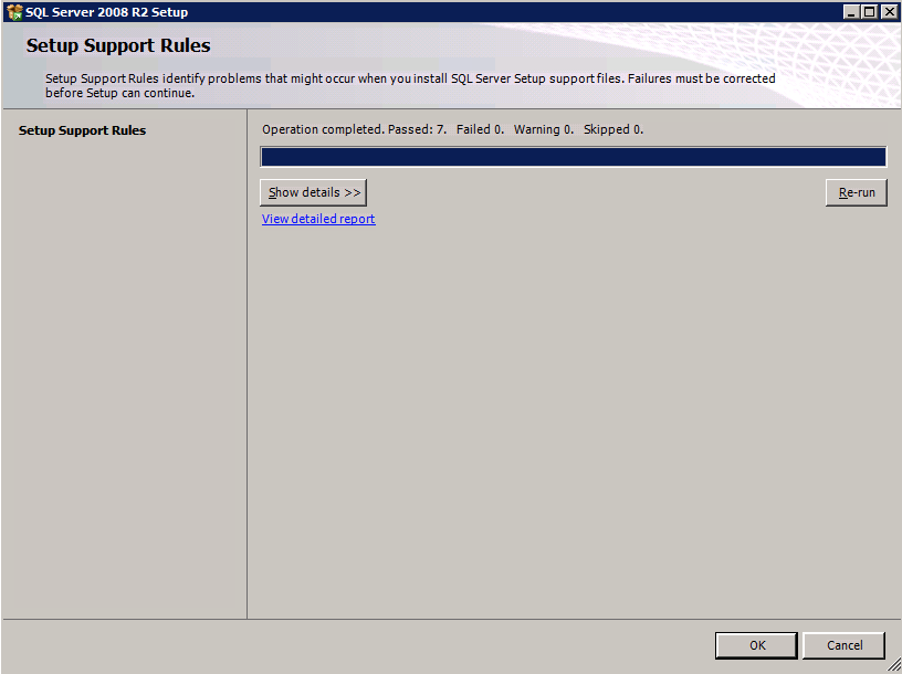
Run the SQL Server setup again on the second node and choose Add node to a SQL Server Failover Cluster.
Congratulations, you are almost done! However, due to Azure’s lack of support for gratuitous ARP, we will need to configure an Internal Load Balancer (ILB) to assist with client redirection as shown in the following steps.
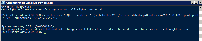
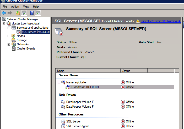
Update the SQL Cluster IP Address
In order for the ILB to function properly, you must run run the following command from one of the cluster nodes. It SQL Cluster IP enables the SQL Cluster IP address to respond to the ILB health probe while also setting the subnet mask to 255.255.255.255 in order to avoid IP address conflicts with the health probe.
cluster res <IPResourceName> /priv enabledhcp=0 address=<ILBIP> probeport=59999 subnetmask=255.255.255.255
NOTE – I don’t know if it is a fluke, but on occasion I have run this command and it looks like it runs, but it doesn’t complete the job and I have to run it again. The way I can tell if it worked is by looking at the Subnet Mask of the SQL Server IP Resource, if it is not 255.255.255.255 then you know it didn’t run successfully. It may simple be a GUI refresh issue, so you can also try restarting the cluster GUI to verify the subnet mask was updated.
After it runs successfully, take the resource offline and bring it back online for the changes to take effect.
Create the Load Balancer
The final step is to create the load balancer. In this case we are assuming you are running the Default Instance of SQL Server, listening on port 1433.
The Private IP Address you define when you Create the load balancer will be the exact same address your SQL Server FCI uses.
Add just the two SQL Server instances to the backend pool. Do NOT add the FSW to the backend pool.
In this load balancing rule you must enable Floating IP
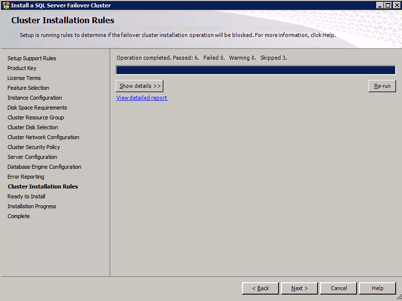
Validate the Cluster
Before you continue, run cluster validation one more time. The Cluster Validation report should return just the same network and storage warnings that it did the first time you ran it. Assuming there are no new errors or warnings, your cluster is configured correctly.
Edit sqlserv.exe Config File
In directory C:\Program Files (x86)\Microsoft SQL Server\100\Tools\Binn we created a sqlps.exe.config file and sqlservr.exe.config with the following lines in the config file:
These files, by default, will not exist and may be created. If this file(s) already exists for your installation, the <supportedRuntime version=”v2.0.50727″/> line simply needs to be placed with the <startup>…</startup> sub-section of the <configuration>…</configuration> section. This should be done on both servers.
Test the Cluster
The most simple test is to open SQL Server Management Studio on the passive node and connect to the cluster. If you are able to connect, congratulations, you did everything correct! If you can’t connect don’t fear, you wouldn’t be the first person to make a mistake. I wrote a blog article to help troubleshoot the issue. Managing the cluster is exactly the same as managing a traditional shared storage cluster. Everything is controlled through Failover Cluster Manager.
Optional – Relocate Tempdb
For optimal performance it would be advisable to move tempdb to the local, non replicated, SSD. However, SQL Server 2008 R2 requires tempdb to be on a clustered disk. SIOS has a solution called a Non-Mirrored Volume Resource which addresses this issue. It would be advisable to create a non-mirrored volume resource of the local SSD drive and move tempdb there. However, the local SSD drive is non-persistent, so you must take care to ensure the folder holding tempdb and the permissions on that folder are recreated each time the server reboots.
After you create the Non-Mirrored Volume Resource of the local SSD, follow the steps in this article to relocate tempdb. The startup script described in that article must be added to each cluster node.
For More Information
As always, if you have questions or comments you can leave them in the comment section below or reach me on Twitter @daveberm
If you have been following my blog, you probably know that I write a lot of step-by-step guides for building SQL Server Failover Cluster Instances (FCI) on Azure, from SQL Server 2008 through the lastest. Here are some links to get you started, but really there is very little difference in the configuration between the different versions of Windows and SQL Server, so I think you will be able to figure it out regardless of what versions you use.
However, that article/video only addresses SQL Server 2016 and later. The good news is that most of that guidance can be applied to SQL Server 2008/2012/2014. Until I have time to do a proper step-by-step guide I wanted to jot down some basic notes, more as a reminder to myself, but you might find this information useful as well in the meantime.
The steps below assume you have already created a SQL Server FCI in Azure and clustered the DTC resource. Reference the guides above for the details on those steps. The steps below really just detail the load balancer configuration required in Azure to make this work.
Create Load Balancer for MSDTC
The MSDTC resource will require its own load balancer. Instead of creating a new load balancer, we will add a new frontend to the load balancer that should already be configured for the SQL Server FCI. Of course this frontend IP address should match the cluster IP address associated with the clustered MSDTC resource.
For the backend pool just reuse the existing pool that you created that contains the SQL cluster nodes.
You will need to create a new health probe dedicated to the MSDTC resource. The port you use has to be different than the one you used for the SQL resource, so don’t use 59999. Instead maybe use something like 49999.
The final step is to create the load balancing rule for MSDTC. Create a new rule and reference the MSDTC frontend that we just created and the existing backend. Next we need to create a new load balancing rule. Since MSDTC uses ephemeral ports, which is a big range of ports, when you create the rule you have to select the box that says “HA Ports”. And finally make sure Direct Server Return is enabled.
Update MSDTC Cluster IP Resource
Just like our SQL Server Cluster IP address, we need to run a Powershell command that will for the MSDTC cluster IP resource to respond to the health probe we just created that probes port 49999. It also sets the subnet mask of that MSDTC cluster IP address to 255.255.255.255 to avoid IP address conflicts with the load balancer frontend we setup that shares the same address.
# Define variables $ClusterNetworkName = “”
# the cluster network name (Use Get-ClusterNetwork on Windows Server 2012 of higher to find the name of the MSDTC resource) $IPResourceName = “”
# the IP Address resource name of the MSDTC resource  $ILBIP = “”
# the IP Address of the Internal Load Balancer (ILB) and MSDTC resource
Import-Module FailoverClusters
# If you are using Windows Server 2012 or higher:
Get-ClusterResource $IPResourceName | Set-ClusterParameter -Multiple @{Address=$ILBIP;ProbePort=49999;SubnetMask="255.255.255.255";Network=$ClusterNetworkName;EnableDhcp=0}
# If you are using Windows Server 2008 R2 use this:
#cluster res $IPResourceName /priv enabledhcp=0 address=$ILBIP probeport=59999  subnetmask=255.255.255.255
Confirm it is working!
You can use DTCPing or go into Component Services and look under Computers>My Computers>Distributed Transaction Coordinator where you should see a local DTC and a clustered DTC. Any distributed transactions should appear in the clustered DTC, not the local DTC. Check out this video for an example of how to create a distributed transaction for testing.
Next Steps
This is a quick and dirty guide, but for the experienced user it should get your MSDTC resource up and running in Azure. I’ll be publishing a detailed step-by-step guide in the near future. In the meantime, if you get stuck don’t hesitate to reach out to me on Twitter @daveberm