I was the principal author of this SIOS whitepaper, which describes how to build a 2-node SQL Server cluster in Google Cloud Platform (GCP) spanning multiple zones. Today, I’ll explain how to extend this cluster by adding a third node in a different GCP region.
Assuming you’ve completed all the steps in the referenced documentation, here’s how to proceed:
1. Create Subnet
Create a new subnet in the additional region.
gcloud compute networks subnets create wsfcnetsub1 \
    --network wsfcnet \
    --region us-west1 \
    --range 10.1.0.0/16
2. Configure Firewall for Internal Communication
Open up firewall rules to allow internal communication on the new subnet.
gcloud compute firewall-rules create allow-all-subnet-10-1 \
    --network wsfcnet \
    --allow all \
    --source-ranges 10.1.0.0/16
3. Verify Available Zones
Check which zones exist in the new region (e.g., us-west1).
gcloud compute zones list \
    --filter="region:(us-west1)" \
    --format="value(name)"
4. Check VM Types Supporting Local SSD
Find the VM types that support local SSD in your target zone.
gcloud compute machine-types list \
    --zones us-west1-a \
    --filter="guestCpus>0 AND name:(n2 n2-highmem n2-highcpu c2 e2-custom e2-custom-memory e2-custom-cpu)" \
    --sort-by=guestCpus
5. Create New VM Instance
Create the new VM in the chosen zone with appropriate settings.
gcloud compute instances create wsfc-3 \
 --zone us-west1-a \
 --machine-type n2-standard-2 \
 --image-project windows-cloud \
 --image-family windows-2016 \
 --scopes https://www.googleapis.com/auth/compute \
 --can-ip-forward \
 --private-network-ip 10.1.0.4 \
 --network wsfcnet \
 --subnet wsfcnetsub1 \
 --metadata enable-wsfc=true \
 --local-ssd interface=nvme \
 --create-disk=auto-delete=yes,boot=no,device-name=extradisk1,size=1,type=pd-standard
6. Set Windows Password
Set a Windows password for accessing the new VM.
gcloud compute reset-windows-password wsfc-3 \
    --zone us-west1-a \
    --user david
7. Configure Windows Networking
On wsfc-3, run these PowerShell commands to configure the network.
# Remove existing DHCP configuration
Remove-NetIPAddress -InterfaceAlias "Ethernet 2" -AddressFamily IPv4 -Confirm:$false
# Set static IP
New-NetIPAddress -InterfaceAlias "Ethernet 2" -IPAddress 10.1.0.4 -PrefixLength 16 -DefaultGateway 10.1.0.1
# Set DNS server
Set-DnsClientServerAddress -InterfaceAlias "Ethernet 2" -ServerAddresses 10.0.0.6
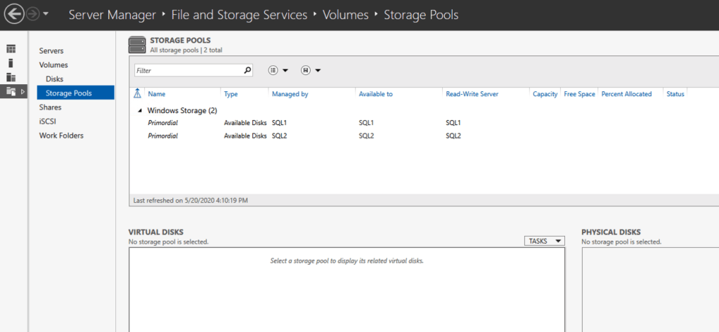
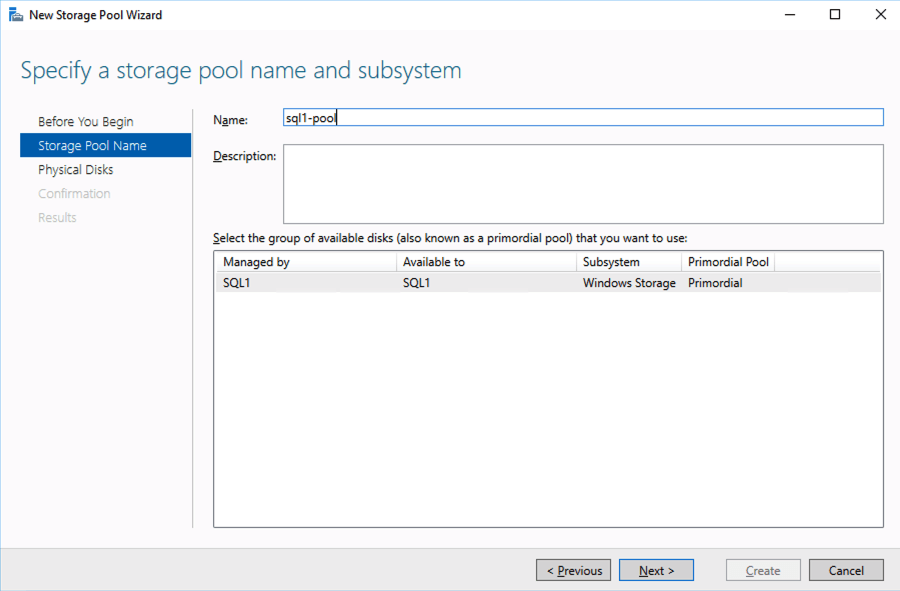
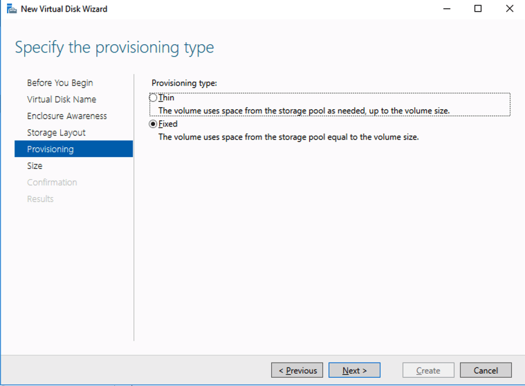
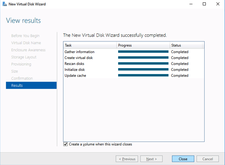
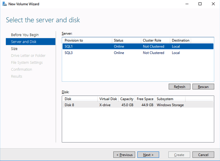
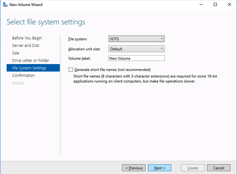
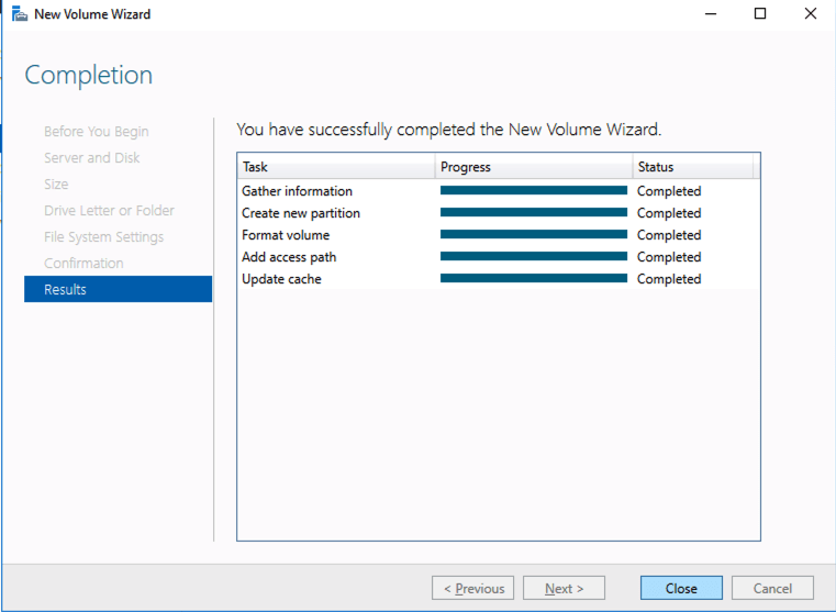
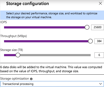
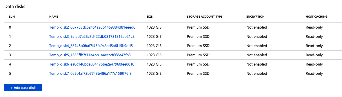
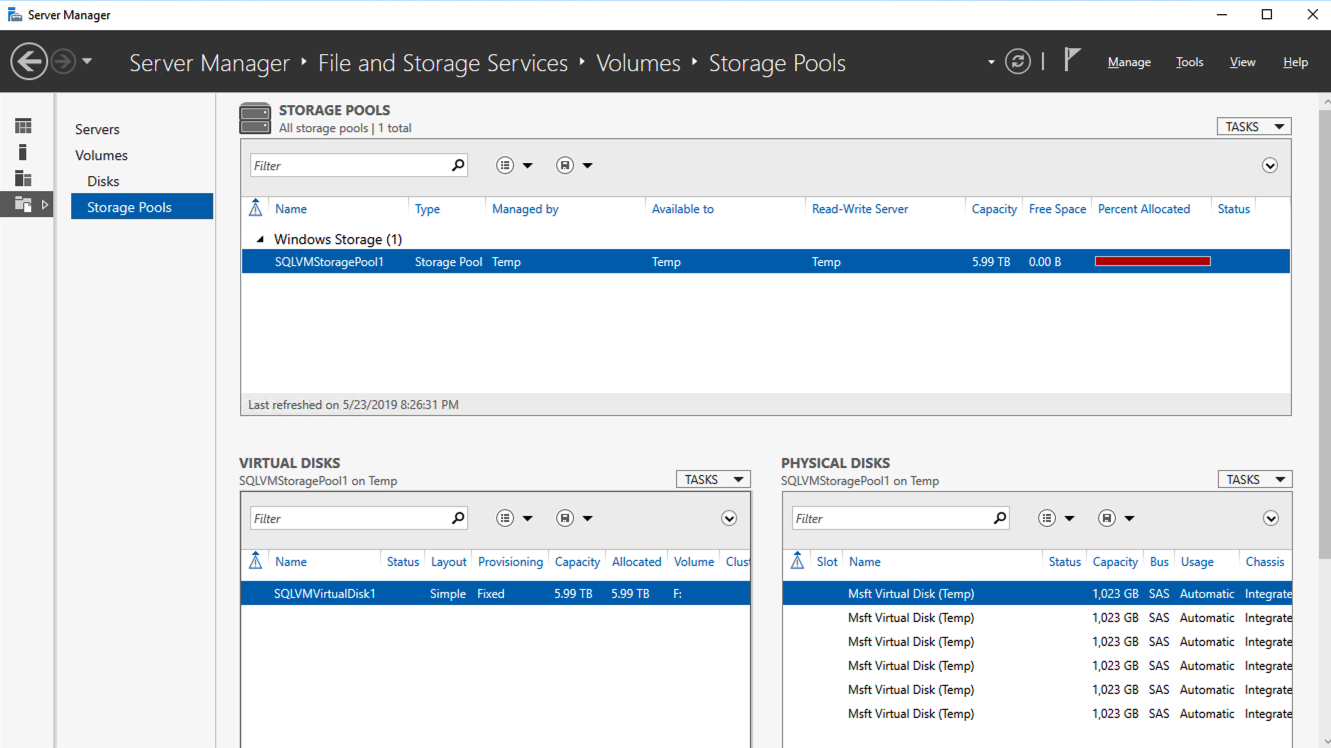
8. Bring Extra Storage Online
Run these PowerShell commands to initialize and format the additional storage.
# Identify the new disk
$disks = Get-Disk | Where-Object IsOffline -Eq $false
$newDisk = $disks | Where-Object PartitionStyle -Eq 'RAW'
# Initialize and format new disk
Initialize-Disk -Number $newDisk.Number -PartitionStyle MBR
New-Partition -DiskNumber $newDisk.Number -UseMaximumSize -AssignDriveLetter | Format-Volume -FileSystem NTFS -NewFileSystemLabel "ExtraDisk"
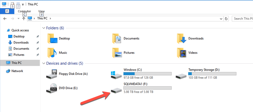
9. Ensure Local SSD Attaches on Startup
Use this script to format and mount the local SSD on startup. Call it AttachSSD.ps1 and save it here. C:\Scripts\AttachSSD.ps1
$diskNumber = 0
$driveLetter = "F"
# Check drive letter availability
if (Get-PSDrive -Name $driveLetter -ErrorAction SilentlyContinue) {
    exit
}
# Initialize and format if RAW
$disk = Get-Disk -Number $diskNumber -ErrorAction SilentlyContinue
while (-not $disk) {

    Start-Sleep -Seconds 5

    $disk = Get-Disk -Number $diskNumber -ErrorAction SilentlyContinue

}
if ($disk.PartitionStyle -eq 'RAW') {

    Initialize-Disk -Number $diskNumber -PartitionStyle GPT

}

$existingPartition = Get-Partition -DiskNumber $diskNumber -ErrorAction SilentlyContinue

if (-not $existingPartition) {

    $partition = New-Partition -DiskNumber $diskNumber -UseMaximumSize -AssignDriveLetter

    Format-Volume -DriveLetter $partition.DriveLetter -FileSystem NTFS -NewFileSystemLabel "LocalSSD"

    Set-Partition -DriveLetter $partition.DriveLetter -NewDriveLetter $driveLetter

}
Schedule Script to Run at Startup:
$taskName = "InitializeLocalSSD"
$scriptPath = "C:\Scripts\AttachSSD.ps1"
$action = New-ScheduledTaskAction -Execute "powershell.exe" -Argument "-NoProfile -ExecutionPolicy Bypass -File `"$scriptPath`""

$trigger = New-ScheduledTaskTrigger -AtStartup

$principal = New-ScheduledTaskPrincipal -UserId "SYSTEM" -LogonType ServiceAccount -RunLevel Highest

Register-ScheduledTask -TaskName $taskName -Action $action -Trigger $trigger -Principal $principal
10. Join the Domain
Join the new server to the domain.
$domain = "datakeeper.local"
$username = "administrator@datakeeper.local"
$password = "YourPassword!"
$securePassword = ConvertTo-SecureString $password -AsPlainText -Force
$credential = New-Object System.Management.Automation.PSCredential ($username, $securePassword)
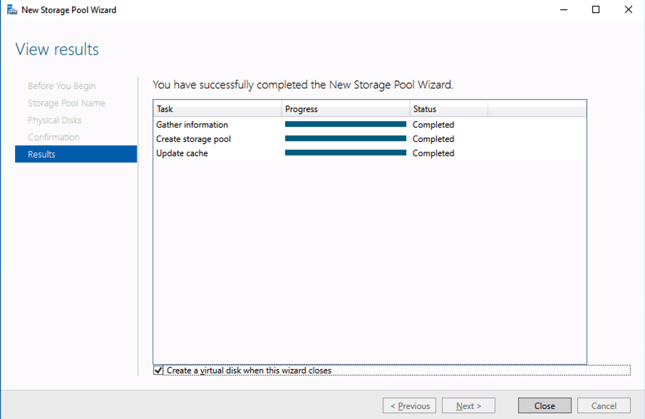
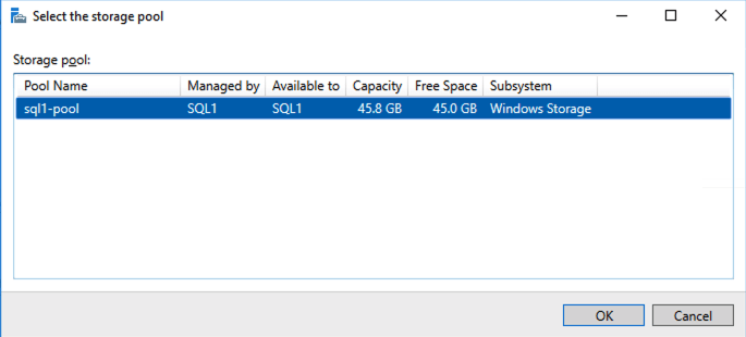
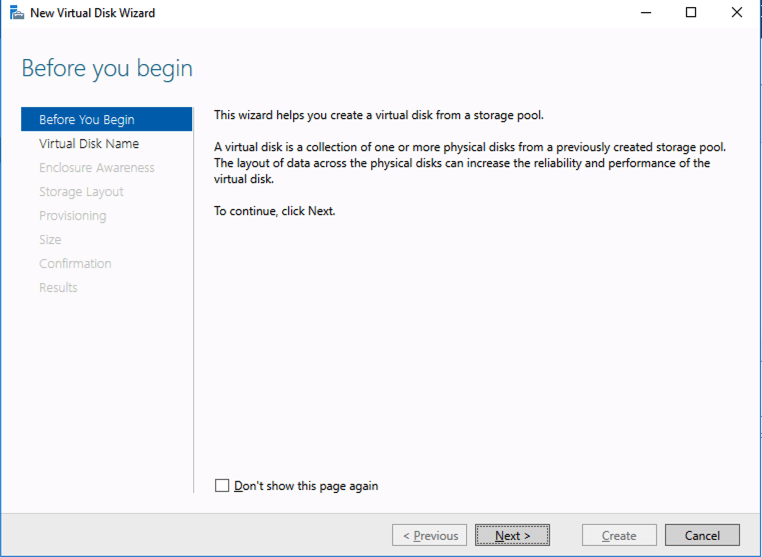
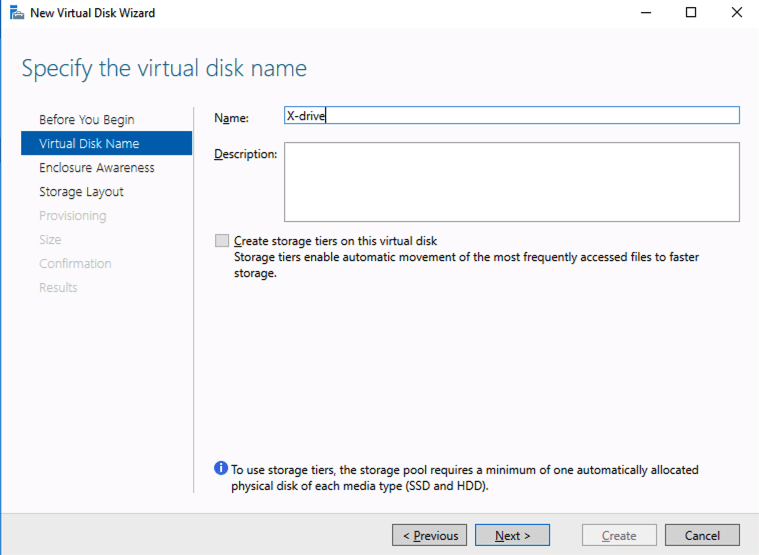
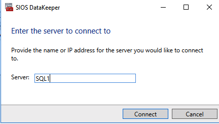
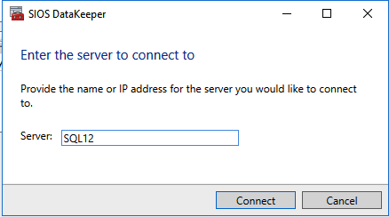
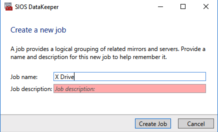
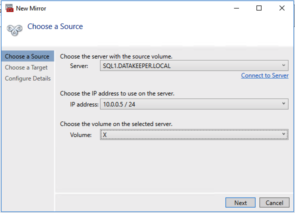
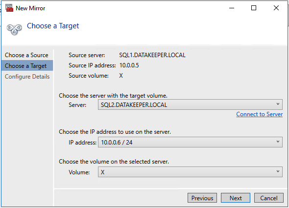
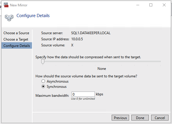
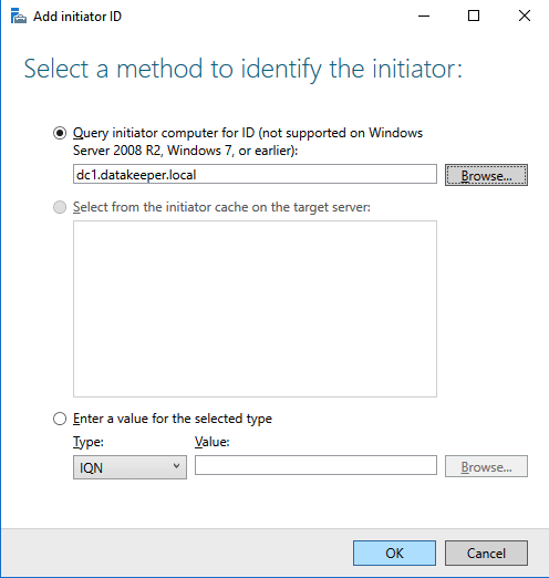
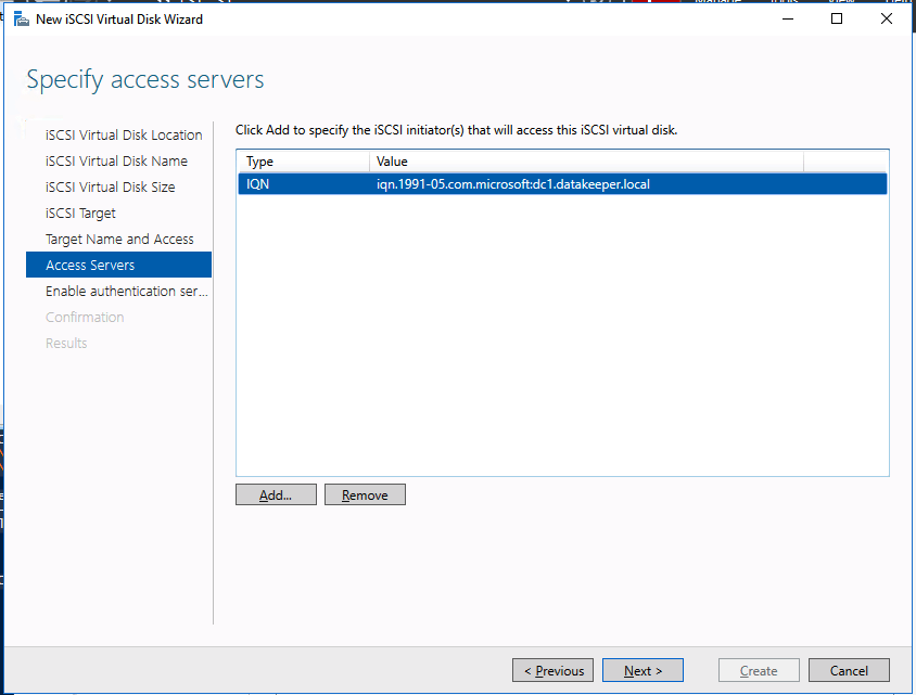
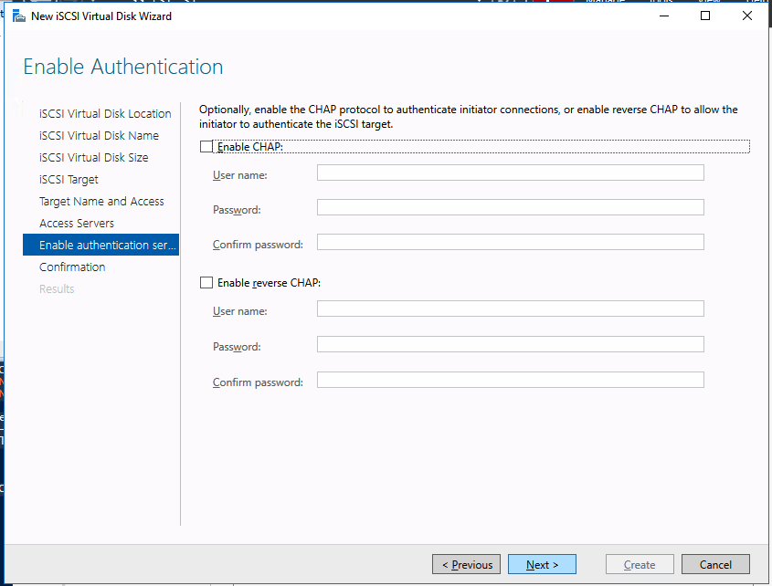
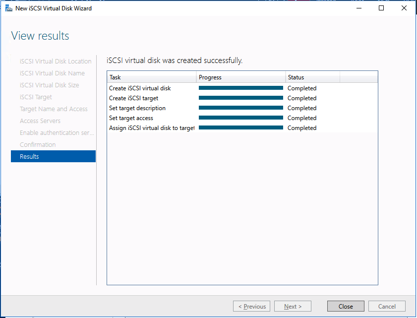
Add-Computer -DomainName $domain -Credential $credential -Force11. Add a new mirror to the existing Datakeeper job
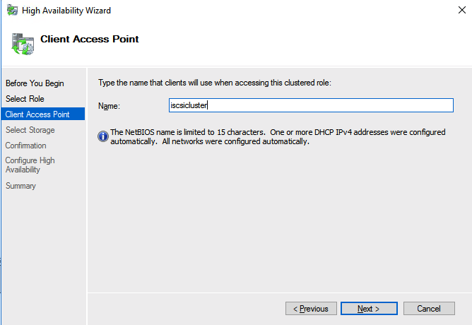
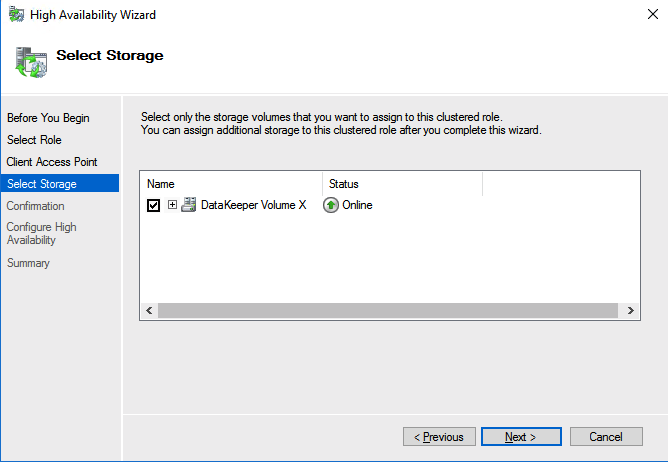
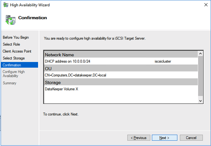
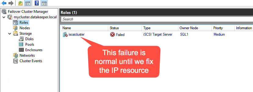
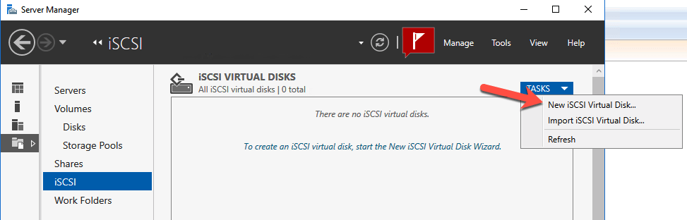
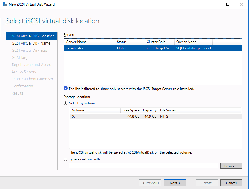
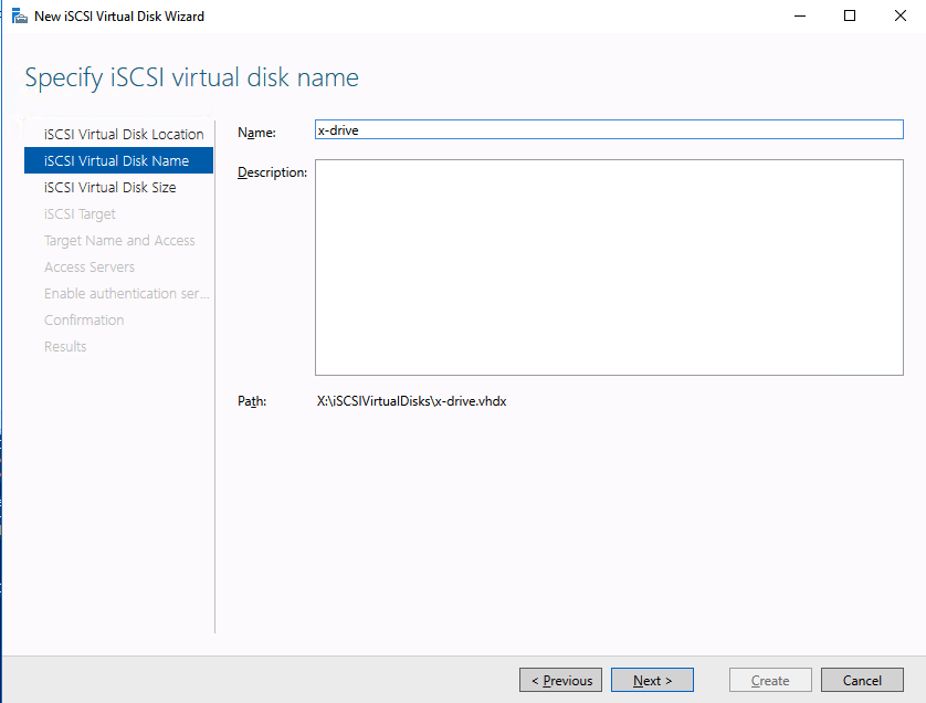
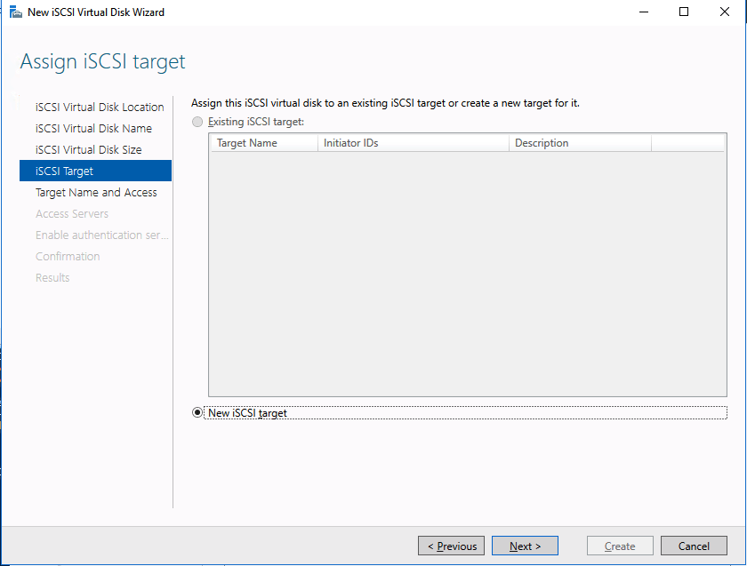
Follow the screenshots below to extend the existing DataKeeper job to the new server.


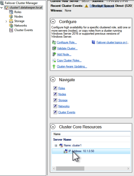
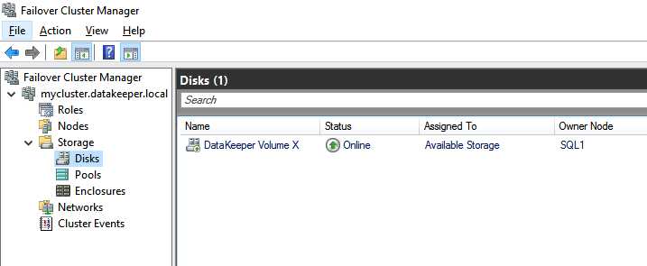
12. Install Windows Failover Clustering and add to the cluster
Install clustering tools and add the node to the cluster.
Install-WindowsFeature -Name Failover-Clustering -IncludeManagementTools
Add-ClusterNode -Cluster fileserver.datakeeper.local -Name wsfc-3

Test-Cluster -Name fileserver.datakeeper.local

Note: Adding the node through the WSFC UI may be necessary if there’s a load balancer issue with the cluster name.
13. Install SQL Server on the new cluster node
Run SQL Server setup and choose add node to existing cluster installation option. https://learn.microsoft.com/en-us/sql/sql-server/failover-clusters/install/add-or-remove-nodes-in-a-sql-server-failover-cluster-setup?view=sql-server-ver16
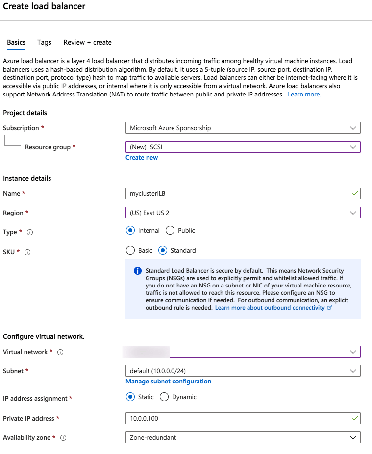
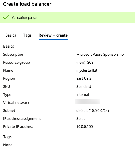
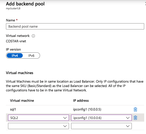
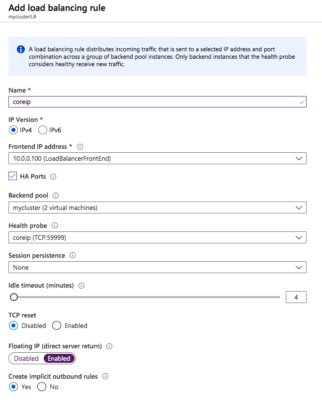
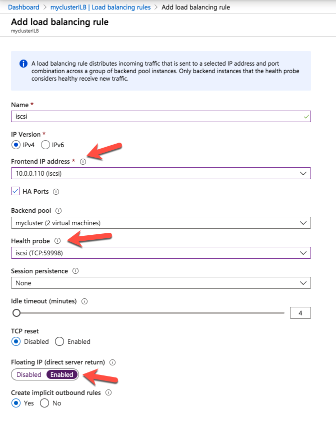
14. Create New Load Balancer Rules
Configure load balancing to allow access across regions.
gcloud compute instance-groups unmanaged create wsfc-group-3 --zone=us-west1-a

gcloud compute instance-groups unmanaged add-instances wsfc-group-3 --instances wsfc-3 --zone us-west1-a

# Set environment variables
export REGION="us-west1"
export NETWORK="wsfcnet"
export SUBNET="wsfcnetsub1"
export LB_NAME="swfc-lbwest"
export HEALTH_CHECK_NAME="wsfc-hc-west"
export HEALTH_CHECK_PORT="59998"
export BACKEND_PORTS="1433"
export BACKEND_IP="10.1.0.9"
export BACKEND_RESPONSE="1"
export LB_INTERNAL_IP="10.1.0.9"

# Step 1: Create Health Check
gcloud compute health-checks create tcp $HEALTH_CHECK_NAME \
 --region=$REGION \
 --port=$HEALTH_CHECK_PORT \
 --check-interval=2s \
 --timeout=1s \
 --unhealthy-threshold=2 \
 --healthy-threshold=2

# Step 2: Create Backend Service
gcloud compute backend-services create $LB_NAME-backend \
 --load-balancing-scheme=INTERNAL \
 --protocol=TCP \
 --region=$REGION \
 --health-checks=$HEALTH_CHECK_NAME \
 --health-checks-region=$REGION

# Step 3: Add Backend Instance Group
gcloud compute backend-services add-backend $LB_NAME-backend \
 --instance-group=wsfc-group-3 \
 --instance-group-zone=us-west1-a \
 --region=$REGION

# Step 4: Create Frontend Configuration (Forwarding Rule)
gcloud compute forwarding-rules create $LB_NAME \
 --load-balancing-scheme=INTERNAL \
 --ports=$BACKEND_PORTS \
 --network=$NETWORK \
 --subnet=$SUBNET \
 --region=$REGION \
 --backend-service=$LB_NAME-backend \
 --ip-protocol=TCP \
 --address=$LB_INTERNAL_IP
 --allow-global-access
Update the original load balancing forwarding rule to allow global access
gcloud compute forwarding-rules update wsfc-lb --region=us-east1 --allow-global-accessThis completes the steps to extend your SQL Server cluster across multiple GCP regions. In the future I’ll probably write a single comprehensive how-to guide, but for now, let me know if you have any questions!